EN
EN

- Overview
- Related Products
- ✔ 1 × HV-BC150 Master Control Box (with display on HV-BC150L)
- ✔ 1 × User Manual & Quick Start Guide
- ✔ 1 × Mounting Accessory Kit (brackets & fasteners)
- ✔ 1 × Communication Cable Set (CAN / RS485)
- ✔ 1 × Factory Test Report & Certificate of Conformance
- ✖ Battery cells / modules
- ✖ High-voltage wiring harnesses
- ✖ Battery cabinet / enclosure
- ✖ PCS (Power Conversion System)
- ✖ External communication gateway (if required)
-
•Inaccurate BMS data
Leads to poor SOC estimation and reduced battery life. -
•Safety risks
Over-charge / over-discharge events can cause thermal runaway. -
•Integration complexity
Compatibility issues with PCS and EMS prolong project timelines. -
•High maintenance costs
Frequent failures and lack of diagnostic tools increase OPEX. -
•Limited customization
Off-the-shelf products don't fit unique system architectures. -
→High-precision sensing
±2mV voltage accuracy & ±0.2% current accuracy for reliable data. -
→Comprehensive protection
3-level alarm & protection (primary, secondary, tertiary) with fast response. -
→Standardized interfaces
CAN, RS485, daisy chain — plug-and-play with major PCS brands. -
→Built-in diagnostics
Event logging, fault recording, and remote monitoring reduce downtime. -
→Full customization
From hardware to software, we tailor solutions to your exact specs. - 1. Verify that the system voltage matches the HV-BC150 rating (1000V DC).
- 2. Ensure all battery connections are properly torqued and insulated.
- 3. Confirm that the mounting surface is flat and capable of supporting the unit weight.
- 4. Prepare communication cables (CAN / RS485) with correct pin assignments.
- 5. Review the user manual for electrical clearance and creepage distance requirements.
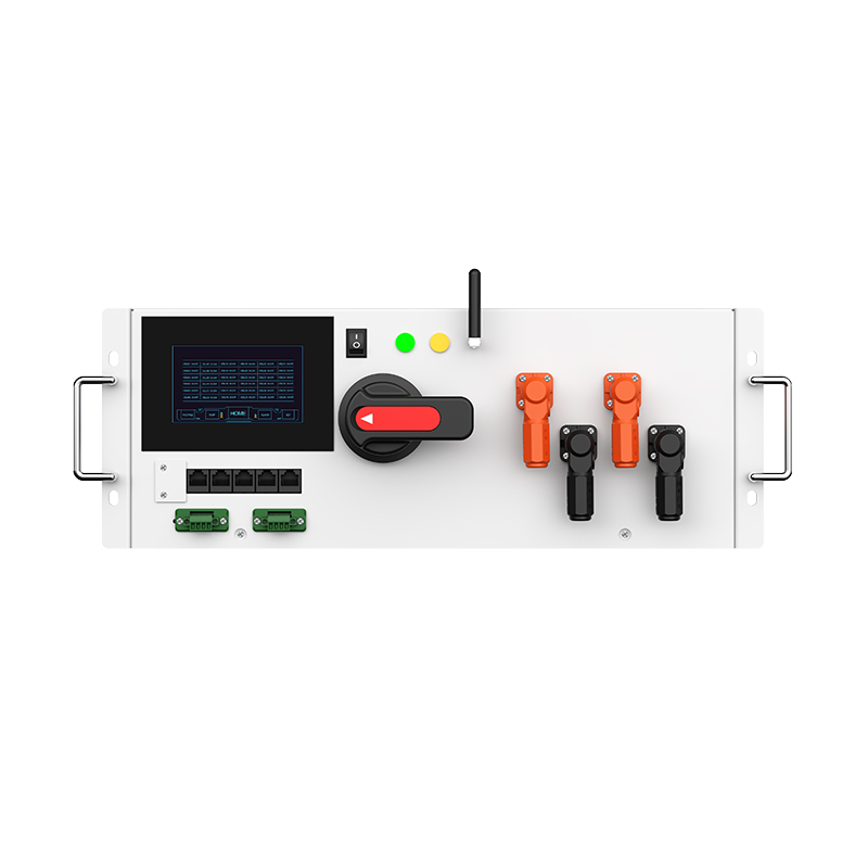
- 1. Mount the HV-BC150 using the detachable hanging ears (hole spacing: 465mm × 101.6mm, Φ6.8 slots).
- 2. Connect BAT+ / BAT- to the battery cluster, and PCS+ / PCS- to the inverter.
- 3. Wire the 24V auxiliary power supply and communication cables as per the pinout.
- 4. Enable the circuit breaker (QSB) to energize the system — observe the pre-charge sequence.
- 5.Safety: Always de-energize before servicing. Use insulated tools and wear PPE.
- Purchase order with model & quantity
- Project specification sheet (voltage, current, communication)
- Shipping address & contact details
- Customization request (if any)
- Communication protocol adaptation
- Custom parameter presets (alarm thresholds, etc.)
- Labeling and branding
- Packaging for bulk or export
- Standard lead time: 15–20 working days
- Shipping: Sea, air, or express (customer's choice)
- Packaging: Export-grade carton with foam protection
- Tracking & insurance provided
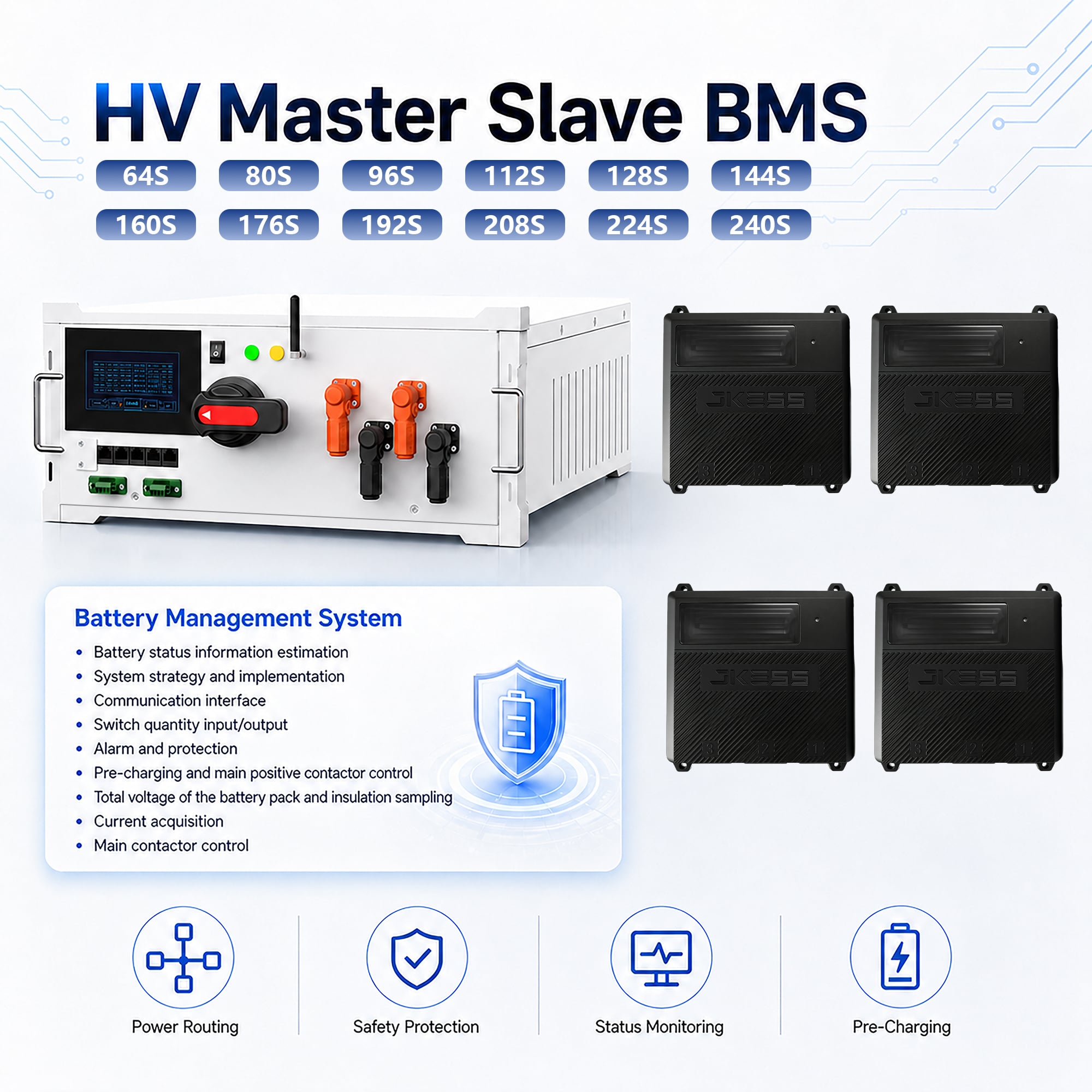
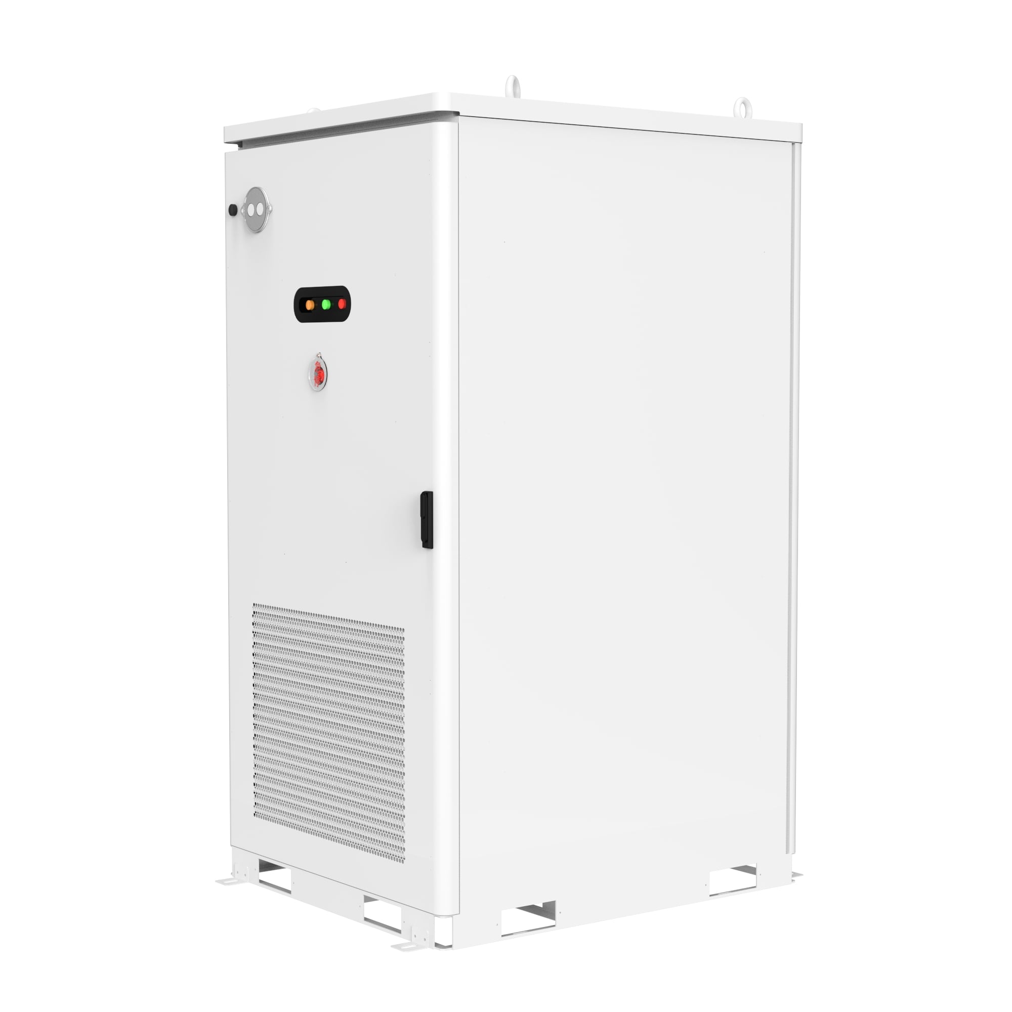
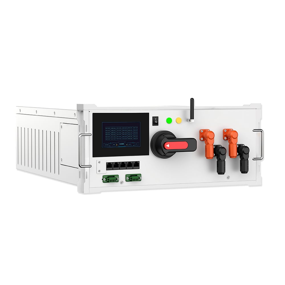
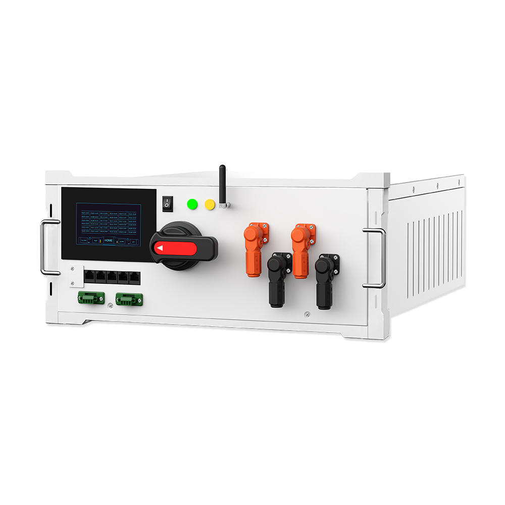
HV-BC150 100A High Voltage BMS Master Box
Precision power routing · Multi-layer safety protection · Real-time status monitoring · Intelligent pre-charging control — engineered for reliable energy storage operations.
Why Choose JKESS
Data-driven value that translates into measurable gains for your energy storage projects.
System Efficiency Boost
Precise cell balancing and intelligent power routing reduce energy loss, improving overall round-trip efficiency.
Fault Rate Reduction
Multi-layer protection (over/under voltage, over-current, temperature) drastically lowers unplanned downtime.
Customization Options
From communication protocols to hardware configurations, we tailor solutions to your specific project needs.
Global Certifications
CE · RoHS · FCC compliant. Independent intellectual property and multiple patents protect your investment.
CERoHSFCC📦 What's in the Box
Clear package contents to help you plan your procurement and installation.
✅ Package Includes
⚠️ Not Included (Sold Separately)
🔑 Key Features
Engineered for precision, built for reliability — the HV-BC150 delivers where it matters.
High-Precision Measurement
Voltage accuracy ≤5mV (±2mV @25°C) & current accuracy ±0.2% for reliable state estimation.
Multi-Layer Protection
Over-voltage, under-voltage, over-current, short-circuit, temperature, and leakage protection.
Active Balancing
Efficient active balancing maintains cell consistency, extending battery pack lifespan.
Flexible Communication
CAN, RS485, and daisy chain interfaces for seamless integration with PCS, EMS, and gateways.
Intelligent Thermal Management
Multiple temperature sensors with active fan control keep battery pack within optimal range (15–30°C).
Pre-Charge Control
Automatic pre-charge sequence with fault detection ensures safe high-voltage connection.
Real-Time Monitoring
Comprehensive data collection (voltage, current, temperature, SOC, SOH) with event & fault logging.
Modular & Scalable
Designed for distributed energy storage systems — compatible with 1000V DC architecture.
🎯 Pain Points & Solutions
We understand the challenges of energy storage integration — here's how the HV-BC150 addresses them.
⚠️ Common Pain Points
✅ How HV-BC150 Solves
JKESS One-Stop Service — Standardized products · Custom engineering · Technical support · Full-cycle after-sales
🏭 Applications
Versatile deployment across the energy storage ecosystem.
Commercial & Industrial Storage
Peak shaving, load shifting, and backup power for factories, data centers, and retail facilities.
Grid-Side Energy Storage
Frequency regulation, voltage support, and renewable integration for utility-scale projects.
Battery System Integration
Turnkey BMS solution for battery pack manufacturers and system integrators.
Community & Microgrid Storage
Distributed storage for residential complexes, islands, and remote off-grid communities.
📋 Technical Specifications
Complete technical data for engineering evaluation and system design.
| Product Model | HV-BC150 |
|---|---|
| Rated Voltage | 1000V DC |
| Rated Current | 100A (continuous) |
| Operating Voltage Range | DC 0–1000V, AC 220V (auxiliary) |
| BMS Architecture | Two-layer (BCU master + BMU slaves) |
| Balancing Mode | Active balancing |
| Voltage Measurement Accuracy | ≤5mV (±2mV @25°C), sampling ≤15ms |
| Current Measurement Accuracy | ±0.2% (@ -20A~+20A), 0.5% (@ -400A~+400A), sampling ≤20ms |
| Temperature Measurement | ±1°C accuracy, sampling ≤5s |
| Communication Interfaces | CAN, RS485, Daisy Chain |
| State Estimation (SOC/SOH) | SOE accuracy ≤5%, energy calculation error ≤3% |
| Protection Levels | Primary / Secondary / Tertiary alarms with contactor control |
| Operating Temperature | 10–30°C (optimal), with thermal management |
| Dimensions (D×W×H) | 482 × 398 × 175 mm (including brackets) |
| Color | RAL7035 (fine-textured frosted finish) |
| MTBF | ≥40,000 hours |
| Certifications | CE, RoHS, FCC (compliant) |
| Standards Compliance | GB/T 34131-2023, GB/T 36558-2018, and others |
🔧 Installation Notes
Key considerations for a safe and efficient installation.
📌 Pre-Installation Checklist
⚡ Key Steps & Safety
🧭 Selection Guide
Choose the right configuration for your project requirements.
🔍 Identify Your System
Battery voltage, capacity, and cell configuration (series/parallel).
↓📊 Define Communication
Select CAN, RS485, or daisy chain — confirm PCS/EMS compatibility.
↓📦 Choose Model
HV-BC150 (no display or with display) for local monitoring.
↓📝 Ordering Guide
Everything you need to know before placing your order.
📋 Documents Required
⚙️ Customization Options
🚚 Delivery & Transport
🔗 Recommended Products
Complete your energy storage system with these JKESS solutions.
HV Slave BMS
Distributed slave control units for cell voltage & temperature monitoring.
View Details →HV Battery Box Kits
Complete battery pack solutions with integrated BMS and thermal management.
View Details →Containerized BESS
Turnkey containerized energy storage systems for utility and commercial projects.
View Details →EMS & Monitoring Platform
Cloud-based energy management with real-time data and remote control.
View Details →❓ Frequently Asked Questions
Quick answers to the most common questions from our B2B clients.
📰 Industry News
Stay informed on the latest developments in energy storage and BMS technology.
EU sets energy storage capacity targets
22 EU members reach an agreement, targeting annual new storage additions of 30–35GW between 2026 and 2028, with a 200GW capacity goal by 2030. Authorities will simplify approvals and financing mechanisms.
Read more →Switzerland plans cross-border long-duration storage
An 800MW/1600MWh flow battery project is arranged at a transnational power hub. Combined with data centre and heating services, the project is expected to operate in summer 2028.
Read more →Germany shifts to longer-duration battery storage
Developers prefer 4-hour storage systems instead of traditional 1–2-hour units to relieve renewable power surplus and negative electricity prices.
Read more →Ireland reforms power market for energy storage
Dynamic 30-minute bidding replaces long-term auctions for frequency regulation. Grid connection delays remain the main barrier for storage projects.
Read more →Spain upgrades policies to boost storage deployment
Spain raises its 2030 storage target to 22.5GW. Storage projects gain priority in land review, environmental assessment and grid connection.
Read more →