
 EN
EN
JKESS Engineering · BMS Guide
Get a Quote →Active vs Passive Balancing BMS: When Does 2A Active Balancing Actually Pay Off?
Passive balancing is not “bad” — it’s just ineffective on LiFePO4’s flat voltage curve. Here are the three specific scenarios where 2A active balancing changes the economics of your battery pack.
Key Takeaways
- Passive balancing is not an inferior solution. It has served lead-acid and earlier lithium battery chemistries for decades, but its effectiveness drops sharply on LiFePO4’s flat voltage curve.
- Between 20% and 80% SOC, LiFePO4 voltage changes only from 3.20V to 3.30V (Δ = 100mV). In this region, passive balancing can barely identify or correct cell-to-cell differences.
- Active balancing is not always worth the investment. For packs built with well-matched Grade A cells and uniform temperatures, passive balancing is the standard solution in more than 90% of grid-connected commercial systems.
- 2A active balancing pays off in three scenarios: large-capacity cells with significant initial dispersion, second-life batteries, and packs with severe temperature gradients.
- The JKESS BMU-H5-16 provides a quantifiable technical solution for these scenarios with 2A active balancing, ±0.005V sampling accuracy, and 8 NTC temperature sensors.
The starting point
Why the Active vs Passive Debate Is Misunderstood
In the energy storage industry, “active balancing is better than passive balancing” has almost become a slogan that needs no explanation. But this conclusion overlooks a critical condition: the effectiveness of a balancing strategy depends on the cell chemistry and operating conditions. Active balancing is not automatically the better investment.
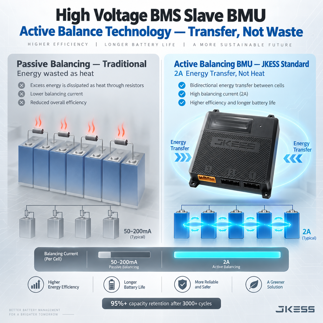
In lead-acid and earlier ternary lithium batteries, the voltage curve has a steeper slope. Passive balancing dissipates excess charge from higher-voltage cells at 50–200mA near the end of charging, which is enough to maintain cell consistency. LiFePO4, however, has an exceptionally flat voltage curve between 20% and 80% SOC — just 100mV separates 3.20V and 3.30V. Within this region, passive balancing can barely identify SOC differences between cells, let alone correct them effectively.
The real question is therefore not “Is active balancing better?” It is: Is passive balancing sufficient for your specific application? And if not, can 2A active balancing deliver a measurable return?
The engineering comparison
How They Actually Work: A Technical Comparison
| Passive Balancing | Active Balancing |
|---|---|
| Operating principleDissipates excess charge from higher-voltage cells as heat through resistors. | Operating principleTransfers charge between cells through inductive DC-DC conversion. |
| Where the energy goesWasted as heat; energy efficiency: 0%. | Where the energy goesTransferred to lower-voltage cells; energy efficiency: 80–95%. |
| Typical balancing current50–200mA. | Typical balancing current1–5A; JKESS BMU-H5-16 delivers 2A. |
| Operating windowOnly during the final charging stage, in the high-SOC region. | Operating windowThroughout charging and discharging, across the entire SOC range. |
| Effectiveness on LiFePO4Almost ineffective in the flat 20%–80% SOC region. | Effectiveness on LiFePO4Effective across the entire SOC range. |
| Heat generationLocalized heat at the balancing resistors. | Heat generationVery low. |
| Circuit complexityLow: resistors and switches. | Circuit complexityHigh: inductors, capacitors, MOSFETs, and control ICs. |
| CostLow. | CostHigher, although the cost gap is narrowing. |
| Impact of the weakest cellThe weakest cell determines usable pack capacity. | Impact of the weakest cellAfter balancing, usable capacity is determined by the average cell level. |
| 314Ah cell · 0.5% differenceApproximately 7.85 hours at 200mA; the limited operating window makes actual time longer. | 314Ah cell · 0.5% differenceApproximately 47 minutes at 2A; balancing can operate throughout charging and discharging. |
Where the economics change
The Three Scenarios Where 2A Active Balancing Actually Pays Off
Active balancing is not worth the investment in every application. In the following three scenarios, the capacity retention and extended service life provided by 2A active balancing can be quantified as direct financial returns.
Large-Capacity Cells with Significant Initial Dispersion
The challenge: When purchasing 280Ah–314Ah large-capacity cells, initial differences of 1%–3% in capacity and internal resistance may exist even within the same batch. In a 16S string, the weakest cell limits usable pack capacity, and the differences can accumulate with cycling.
The value of 2A active balancing: It can quickly eliminate initial dispersion during commissioning, avoiding the capacity loss caused by the weakest-cell bottleneck. With 2% initial dispersion, passive balancing may need weeks to complete the first balance, while 2A active balancing can complete it in hours.
Quantified return: In a 64kWh system, eliminating a 2% initial capacity loss makes an additional 1.28kWh available. At one cycle per day over a 10-year life, that amounts to approximately 4,672kWh of additional cumulative throughput.
Second-Life or Repurposed Batteries
The challenge: Batteries recovered from different vehicles or batches have much greater variation in capacity, internal resistance, and self-discharge rate than new cells. Passive balancing can barely maintain consistency in such highly dispersed packs.
The value of 2A active balancing: Its higher balancing current can continuously compensate for significant cell-to-cell differences, bringing the usable capacity of a second-life battery pack close to that of a new pack.
Quantified return: Second-life batteries typically cost 40%–60% of new batteries to purchase. With active balancing increasing usable capacity by 10%–20%, project internal rate of return (IRR) improves significantly.
Battery Packs with Severe Temperature Gradients
The challenge: In rack-mounted energy storage systems, cells at the top and bottom can differ by 5–10°C. Temperature differences lead to different self-discharge rates and, consequently, SOC drift. Passive balancing cannot effectively correct this under temperature-gradient conditions.
The value of 2A active balancing: Continuous operation throughout charging and discharging compensates for temperature-driven SOC drift. With 8 NTC temperature sensors, the BMU-H5-16 can monitor temperature distribution in real time and trigger balancing strategies.
Quantified return: Research indicates that maintaining a cell-to-cell temperature difference below 3°C can extend battery pack life by 15%–20%.
The other side of the decision
When Passive Balancing Is Still the Right Choice
For grid-connected commercial systems using well-matched Grade A cells — capacity variation below 0.5% and internal resistance variation below 5% — with a uniform pack temperature distribution of less than 2°C difference, passive balancing is the standard and sufficient solution in more than 90% of cases.
The key selection criterion is not the absolute superiority of “active versus passive.” It is the combination of initial cell dispersion, operating temperature gradient, and the system’s sensitivity to capacity retention. When all three variables are controlled, passive balancing’s simplicity and lower cost become stronger advantages.
The hardware behind the strategy
BMU-H5-16: The 2A Active Balancing Slave BMU Inside JKESS HV Systems
| Parameter | Value | Notes |
|---|---|---|
| Balancing method | Active balancing (inductive DC-DC conversion) | Energy is transferred between cells rather than dissipated as heat. |
| Maximum balancing current | 2 A | Per channel. |
| Maximum cell sampling count | 16 | 16S LiFePO4. |
| Voltage sampling range / accuracy | 1–4.5V / ±0.005V | 5mV accuracy. |
| Temperature sampling inputs | 8 NTC channels | — |
| Temperature sampling range / accuracy | −30 to 105°C / ±2°C | — |
| High-side channels / continuous capability / maximum output | 2 / 1A / 3A at 300ms | — |
| Cooling method | Intelligent air cooling / controllable fan cooling | Integrated into the front panel. |
| Communication interfaces | CAN / RS485 / daisy chain | To the HV master control box. |
| Cell chemistry | LiFePO4 | Supports 280Ah–314Ah prismatic cells. |
| Battery box voltage range | 100V–800V DC (depending on series count) | Expanded through multiple boxes connected in series. |
Scroll horizontally to view all specification columns.
Specification source: JKESS HV Slave Battery Box product page and brochure sheet.
Know the limits
3 Common Misconceptions About Active Balancing
“Active balancing can repair a damaged cell.”
Active balancing can only transfer charge; it cannot restore a cell’s chemical capacity. If a cell’s capacity has already degraded severely, active balancing can only delay its impact, not reverse the degradation.
“A higher balancing current is always better.”
A 2A balancing current is reasonable for cells in the 300Ah class, but excessively high balancing current increases circuit complexity and cost. Select balancing current to match cell capacity and system operating conditions.
“Active balancing means cell screening is unnecessary.”
Active balancing can compensate for cell differences, but it cannot eliminate extreme initial inconsistency. Buyers should still request batch-level capacity and internal resistance consistency data from their cell supplier.
From BMU to complete system
How to Configure JKESS HV Systems with 2A Active Balancing
JKESS modular high-voltage energy storage systems use the BMU-H5-16 as the slave control core, paired with an HV-BC250 (200A) or HV-BC150-100A (100A) master control box. They support 4–16 slave boxes (HV-B6U or 4U Kits), system capacities of 64–256kWh, and a voltage range of 80–1000V.
| System capacity |
Slave boxes |
Series count |
Nominal voltage |
Master control box option |
|---|---|---|---|---|
| 64 kWh | 4 | 64S | ~204.8V | HV-BC150-100A |
| 96 kWh | 6 | 96S | ~307.2V | HV-BC150-100A |
| 128 kWh | 8 | 128S | ~409.6V | HV-BC150-100A |
| 192 kWh | 12 | 192S | ~614.4V | HV-BC250 |
| 256 kWh | 16 | 256S | ~819.2V | HV-BC250 |
Scroll horizontally to view all five configuration columns.
Buyer questions, answered
Frequently Asked Questions
Is active balancing always better than passive balancing?
No. Active balancing is more effective on LiFePO4’s flat voltage curve and in scenarios with high cell-to-cell variation, but passive balancing remains the standard and sufficient solution for more than 90% of grid-connected commercial systems using well-matched Grade A cells with uniform temperature distribution. The right choice depends on cell initial dispersion, operating temperature gradient, and sensitivity to capacity retention.
Why does passive balancing fail on LiFePO4?
LiFePO4 has an extremely flat voltage curve between 20% and 80% SOC — only about 100mV variation (3.20V to 3.30V). Passive balancing relies on voltage differences to identify which cells need discharging, but in this flat region, voltage differences are too small to accurately reflect SOC differences. Passive balancing also only operates during the final charging stage, further limiting its effectiveness.
How long does 2A active balancing take to correct cell imbalance?
For a 314Ah LiFePO4 cell with 0.5% capacity variation, the energy to be balanced is approximately 1.57Ah. At 2A active balancing current, this takes about 47 minutes. At 200mA passive balancing, the same energy transfer would take approximately 7.85 hours — and passive balancing only works during the final charging stage, so actual time is even longer.
What are the three scenarios where 2A active balancing pays off?
The three scenarios are: (1) large-capacity cells with significant initial dispersion (1%–3% capacity variation), (2) second-life or repurposed batteries with high cell-to-cell variation, and (3) battery packs with severe temperature gradients (5–10°C difference between top and bottom cells). In these scenarios, 2A active balancing can recover 1–2% of usable capacity and extend pack life by 15%–20%.
Does JKESS BMU-H5-16 support active balancing?
Yes. The BMU-H5-16 is JKESS’s active balancing slave BMU, delivering up to 2A balancing current per channel using inductive DC-DC conversion. It supports 16S LiFePO4 cells with ±0.005V cell voltage sampling accuracy and 8 NTC temperature sensors. It is pre-installed in all JKESS HV slave battery box kits.
Can I retrofit active balancing into an existing passive balancing system?
Retrofitting is technically possible but often impractical because active balancing requires different wiring, different BMS hardware, and different communication protocols. The more cost-effective approach is to select a system that includes active balancing from the start — especially if your application falls into one of the three high-variation scenarios.
How does active balancing affect battery pack warranty?
Active balancing helps maintain cell consistency, which directly protects capacity retention. If a warranty guarantees a minimum capacity retention (e.g., 70% at 10 years), active balancing improves the likelihood that the pack meets that threshold by reducing the rate of imbalance-driven degradation.
What is the typical cost difference between passive and active balancing BMS?
Active balancing BMS hardware typically costs 20%–40% more than passive balancing equivalents at the component level. However, in the three high-variation scenarios, the additional usable capacity and extended pack life can deliver a return on that premium within 2–3 years of operation.
Does active balancing work during both charging and discharging?
Yes. Unlike passive balancing, which only operates during the final charging stage (high SOC), active balancing operates continuously during both charging and discharging across the entire SOC range. This is particularly important for LiFePO4 because its flat voltage curve means passive balancing has very limited windows of effectiveness.
How does JKESS support B2B customers evaluating active balancing?
JKESS provides modular HV BESS hardware including the BMU-H5-16 active balancing slave BMU, HV-BC250 (200A) and HV-BC150-100A (100A) master control boxes, and HV-B6U / 4U slave battery box kits. The system supports 4–16 slave boxes (64–256kWh) with CAN/RS485/daisy-chain communication. JKESS does not sell cells; buyers source LiFePO4 cells separately, allowing system design to be optimized around specific cell specifications.
Not Sure If Active Balancing Is Right for Your Project?
Share your cell specifications and operating conditions with our engineering team. We’ll help you determine whether 2A active balancing delivers a measurable return for your specific application.
Request a Custom Quote →