
 EN
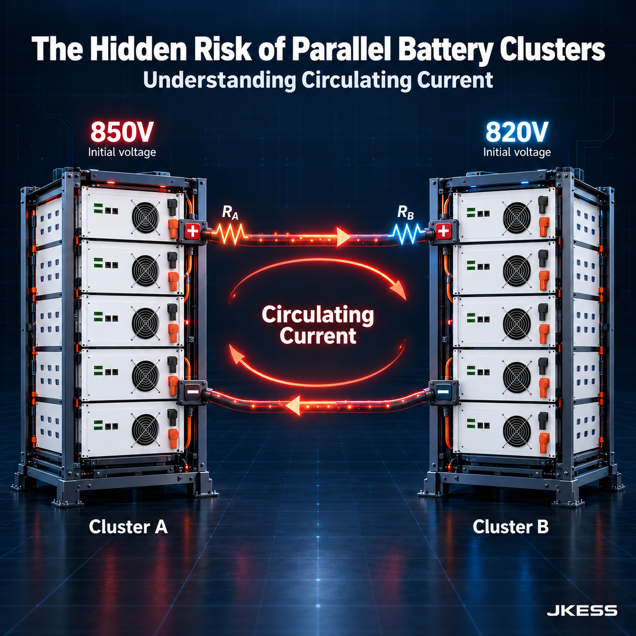
Circulating Current in Parallel Battery Strings: Why It Happens and How BMS Architecture Prevents It
Parallel battery strings are not plug-and-play. A voltage difference of just a few volts creates a circulating current that reduces efficiency, accelerates aging, and can trigger protection faults. Here is the physics — and the three engineering countermeasures that make parallel expansion safe.
Key Takeaways
- Circulating current is an important hidden risk in BESS expansion projects. A normal total-current reading can conceal energy moving between parallel battery strings.
- The physics: current flows from the higher-voltage source into the lower-voltage string. In a simplified resistive model, circulating current equals voltage mismatch divided by loop resistance. A few volts can drive tens of amperes in a low-resistance loop.
- Three contributors deserve attention: SOC differences, capacity or internal-resistance differences, and temperature differences. Mixing new and aged batteries can combine all three.
- Three measures work together: independent breakers and fuses with controlled string isolation; BMS current monitoring in charge, discharge, and standby; and supervisory management that limits voltage and SOC mismatch before connection and during operation.
- JKESS describes 4–16 slave boxes per master in a daisy chain. This is a module-management topology. Safe parallel expansion additionally requires independent protection, sensing, and an approved control strategy for every parallel string.
The Expansion Scenario That Goes Wrong
Consider an illustrative commercial and industrial (C&I) expansion: a factory installs a 128kWh battery system in 2024 and needs 256kWh in 2026 as its load grows. Procurement proposes buying another identical system and connecting it in parallel. Three months later, the operations team notices persistent current imbalance and a faster reported SOC decline in one string. The model numbers match, but the batteries no longer have the same operating history.
Circulating current is one possible explanation, alongside unequal load sharing, temperature differences, connection resistance, sensor error, or cell faults. New and aged strings can have different capacities and internal resistances, so their internal voltage and SOC trajectories diverge during operation even if their initial SOC readings match. A higher source voltage can then drive current into the other string. Check signed branch currents and cell data before diagnosing the cause.
Uncontrolled internal transfer creates resistive losses and extra battery throughput. It can increase thermal and cycling stress, cause cell-voltage limits to be reached, and trigger BMS protection; sufficiently high currents may operate a fuse or breaker. Some problems appear at the instant of connection, while others become clearer over weeks of operating data. This guide explains the physics, three engineering countermeasures, and the role of JKESS master and slave hardware in an engineered parallel-string design.
The Physics: Why Circulating Current Happens
Circulating current does not by itself prove poor battery quality. It follows circuit laws when parallel sources have different internal voltages. A useful first estimate for two strings at zero external load is:
I_circulating = ΔV / R_loop- ΔV
- Open-circuit voltage difference before connection, or equivalent internal-source voltage difference between strings, in volts (V).
- R_loop
- Total effective loop resistance, in ohms (Ω): both strings’ internal resistances plus cable, busbar, connector, and contact resistances.
Once connected, the strings share a common bus voltage, apart from interconnect voltage drops. The driving mismatch is between their equivalent sources, not two different voltages at the same ideal bus node. Under external load, each branch current includes load sharing as well as the effect of voltage mismatch. This resistive estimate does not model connection transients, inductance, or electrochemical relaxation.
Worked example: a small mismatch, a substantial current
Assume a 2V source-voltage mismatch and a total loop resistance of 0.05Ω. These are illustrative inputs, not a typical resistance or a connection acceptance limit.
2V ÷ 0.05Ω = 40AThe higher-voltage string discharges; the lower-voltage string charges. Energy transfers between batteries while part of it is dissipated as heat in the loop:
P_loss = I² × R_loop = 40² × 0.05 = 80WThis current supplies no external load. Simple equalization tends to reduce the initial voltage difference; it is not inherently a self-amplifying loop. Unequal aging, cell condition, and operating histories can nevertheless create recurring imbalance.
| Source | Mechanism | In an expansion project |
|---|---|---|
| SOC differences | Different states of charge can produce different source voltages. The SOC-to-voltage relationship depends on chemistry and operating history. | A fully charged new string connected to an existing string at 80% SOC can create an immediate equalization current. |
| Capacity / internal-resistance differences | Different capacities and resistances change branch current, voltage drop, and the rate of SOC change. | New and aged strings share current unequally and follow different SOC trajectories during charge and discharge. |
| Temperature differences | Temperature affects resistance, available capacity, voltage response, and self-discharge over time. | A string near a heat source or with poor airflow can behave differently from one in a cooler location. |
Engineering reference: Weng et al., research on current imbalance in dissimilar parallel-connected batteries, develops an equivalent-circuit model and examines how capacity and resistance differences affect current, SOC, and aging. The numerical example above is an illustrative circuit calculation, not a product test result.
Unprotected Parallel vs Independent String Protection
Independent branch protection makes faults easier to detect and isolate. It must be paired with per-string sensing and a coordinated control response; protection devices alone do not eliminate circulating current.
| Unprotected Parallel | Independent String Protection |
|---|---|
| One shared breaker protects the parallel group. | Each string has a coordinated breaker and fuse. |
| No automatic branch-isolation path interrupts internal transfer. | A BMS-controlled contactor or suitable trip device can isolate a faulted string. |
| A group-level protection trip stops the entire battery group. | Healthy strings may continue if their ratings and the control design permit. |
| Total-current sensing hides which branch is abnormal. | Bidirectional per-string sensing identifies abnormal branch behavior. |
| New and aged strings are combined without mismatch checks. | Voltage and SOC checks govern connection; supervisory controls manage deviations. |
| Individual-string isolation for maintenance is unavailable. | Branch isolation supports planned maintenance under an approved isolation procedure. |
| Protection events have limited branch-level traceability. | String measurements and event logs help trace fuse or breaker operation. |
| Result: hidden internal current, limited fault isolation, and potentially longer downtime. | Result: observable branch behavior, selective isolation, and better availability when properly coordinated. |
If a string disconnects, the remaining strings can receive more current. The EMS/PCS must reduce power or stop operation when necessary to prevent a cascading shutdown. Independent protection is not permission for live maintenance.
The 3 Engineering Countermeasures
-
Equip every string with independent breakers and fuses
The purpose of branch protection is selective fault isolation. Specify a DC-rated breaker and fuse for each string, together with BMS-controlled contactors or a suitable automatic trip mechanism. A moderate circulating current can remain below an overcurrent trip threshold, so a fuse is not a substitute for controlled isolation.
Selection priorities: coordinate the continuous-current rating, time-current curves, DC voltage rating, available fault current, breaking capacity, conductor protection, and permitted operating peaks. Evaluate fault contributions from every connected string. Selective interruption and continued operation must be verified at system level.
Installation location: use the approved single-line diagram and grounding arrangement to determine which conductors need protection and isolation. There is no universal rule that the breaker belongs on the positive conductor and the fuse on the negative conductor. Confirm the pre-charge and connection sequence for the delivered equipment; a DC-link pre-charge circuit is not automatically rated to equalize mismatched battery strings.
-
Monitor each string in charge, discharge, and standby
Place an independent bidirectional current-sensing channel on every parallel string and retain its sign. A system with only a total-current sensor cannot identify the internal transfer hidden by summation. For example, with discharge positive, +40A in one string and −40A in another gives approximately 0A at the external connection.
Log current with cell voltages, string voltage, temperature, SOC, contactor state, and operating mode. Configure thresholds and time delays around sensor accuracy, expected load sharing, string ratings, and the approved control strategy. Respond with alarms, connection inhibition, power limits, or isolation as appropriate; setting external power to zero may not stop internal current.
For a two-string comparison with currents in the same direction and above the measurement floor, one descriptive imbalance metric is:
Current imbalance (%) =100 × |I1 − I2| / max(|I1|, |I2|)Near standby, use signed amperes and absolute thresholds. Percentages become unstable near zero. Opposite current directions require separate evaluation, and unequal-capacity strings may legitimately carry different currents; compare each branch with its expected allocation and limits.
-
Use master-level supervision to limit SOC and voltage mismatch
SOC mismatch is one contributor to circulating current, but voltage response also depends on resistance, temperature, cell condition, and recent operation. The string masters and system supervisor should exchange validated measurements and limits through the approved CAN/RS485 protocol, then enforce voltage and SOC matching criteria before connecting a branch.
During operation, supervisory control can review deviations, reduce system power, inhibit reconnection, or isolate an unsuitable branch. A 5-percentage-point SOC deviation can be an illustrative review trigger only if accepted for the project; it is not a universal connection threshold. On a directly paralleled DC bus, BMS software cannot independently set each string’s continuous current without suitable power hardware, such as a per-string DC/DC stage.
JKESS describes daisy-chain management of 4–16 slave boxes per master. Combine the appropriate module-management hardware with a defined protection and sensing channel for every parallel string, and confirm the cross-string supervisory functions for the selected firmware and system design. Cell-level active balancing supports consistency within modules; it does not replace inter-string current control.
Architecture reference: Parallel-string application note: protection and topology considerations (PDF). This external engineering reference discusses independent string monitoring, automatic isolation, and topology tradeoffs; it is not evidence of a JKESS product feature or compatibility claim.
How JKESS HV BESS Architecture Manages Parallel Strings
A master box, slave BMUs, and a system-level controller serve different roles. The JKESS master-plus-slave platform provides module measurements, communication, and protection building blocks. A parallel-string project must also define the sensing, isolation, and supervisory control of each complete string.
| JKESS component | Key parameters | Value for circulating-current management |
|---|---|---|
| HV-BC250 200A HV BMS Master | 200A continuous; 80–1000V DC; CAN/RS485 and daisy chain. The overview lists 32–273 series cells; the specification table lists 64–256. | Provides a master-level measurement and protection interface. Confirm the approved series range, 4–16-module configuration, firmware, and per-string protection assembly. |
| HV-B6U 6U Slave Battery Box Kits | 16S LiFePO4; BMU-H5-16; up to 2A active balancing; approximately 28.55kg reference kit weight. | Each box has a BMU for cell-level measurements and balancing. Its data supports the string master’s assessment; it is not an independent cross-string current regulator. |
| HV Slave 4U Kits | 16S LiFePO4 module platform; compact 4U enclosure; BMU-H5-16; no CCS; sensing and temperature harnesses included. | A compact module option for space-constrained rack designs, subject to the required string voltage, cell selection, and protection layout. |
| Modular Stacked System | 4–16 slave boxes per master; 80–1000V platform. Approximately 64–256kWh is an illustrative class using nominal 16kWh modules. | Supports modular system design. Series-module expansion changes voltage; adding a complete parallel string requires separate design approval and branch protection. |
| JKESS261 Liquid-Cooled System | 261.25kWh design configuration; 125kW PCS; 728–936V DC; liquid cooling; EMS integration. | Integrates battery monitoring, thermal management, and system supervision. Confirm the approved DC or AC expansion topology and the supplied parallel-control functions. |
| BMU-H5-16 Active Balancing Slave BMS | Up to 2A balancing; ±0.005V cell-voltage sampling accuracy; 8 NTC temperature channels. | Reduces cell imbalance within the module. It does not move energy directly between complete parallel strings; the link provides master-system context. |
Technical anchors for the system design
- Module management: the modular platform specifies 4–16 slave boxes in a daisy chain per master. The delivered configuration and series cell count must stay within the approved master and PCS voltage limits.
- Cell consistency: BMU-H5-16 uses up to 2A active balancing, ±0.005V voltage sampling, and 8 temperature channels. These are module-level functions.
- Communication: platform references list CAN at 250k/500k and RS485 at 9600/115200. Baud rate alone does not establish protocol interoperability; confirm message definitions and firmware support.
- Branch protection: specify and verify independent string breakers, fuses, bidirectional current sensors, and controlled isolation in the project bill of materials.
- Cells excluded: the JKESS kits described here are supplied without cells. Buyers source LiFePO4 cells and must verify their suitability for the existing installation.
Configuration matters. The master product page publishes two series-cell ranges, so this guide does not treat them as interchangeable. Energy capacity is determined by the selected cells and electrical configuration, not by box count alone. Match the purchase specification to the exact hardware, firmware, and approved system drawing.
Pre-Expansion Checklist: 8 Items Before You Parallel a New String
- Verify electrical matching. Confirm identical approved chemistry and series cell count, compatible voltage windows, and correct polarity. Measure rested string OCVs and use the manufacturer-approved connection limit; ≤2V is not universally safe in a low-resistance loop.
- Review the cells and their condition. Compare model, batch records, capacity, internal resistance, age, state of health, and cell-voltage spread. A matching product label or initial SOC reading does not establish compatibility.
- Confirm independent branch protection. Verify each string’s breaker, fuse, controlled isolation path, fault-current coordination, and approved pre-charge/connection arrangement.
- Validate current sensing. Confirm independent bidirectional sensing for every string, including sensor polarity, zero offset, accuracy, data logging, and standby measurement capability.
- Verify the supervisory strategy. Confirm SOC and voltage acceptance limits, connection permissions, current limits, communication-loss responses, and power reduction after a string disconnects.
- Check thermal conditions. Compare cell and ambient temperatures and inspect airflow or liquid-cooling performance. A temperature difference of ≤3°C can be a project target, not a universal pass/fail threshold; use the approved thermal criteria.
- Complete the specified insulation checks. Qualified personnel must use the equipment-approved isolation procedure, test voltage, and acceptance resistance. A criterion such as ≥1 MΩ at 1,000 VDC applies only when explicitly specified; do not apply a high-voltage insulation test across connected electronics unless the procedure allows it.
- Plan commissioning and follow-up monitoring. Set alarms before connection, verify the approved energization sequence, and log branch current, SOC, cell voltages, and temperatures during an initial 72-hour observation period. Continue trend monitoring afterward.
5 Common Mistakes When Paralleling Battery Strings
-
1. Directly paralleling strings at different SOCs
A full new string and an existing string at 80% SOC can exchange a substantial current on connection. Match voltage and SOC using the approved procedure, and check cell limits as well as pack voltage. Do not use the main contactor to equalize an unapproved mismatch.
-
2. Protecting the entire group with only one breaker
A shared breaker cannot provide selective isolation for each branch. Specify coordinated per-string breakers and fuses plus a controlled disconnection mechanism. Moderate internal currents may never reach a fuse’s operating threshold.
-
3. Monitoring only total battery current
The total can look normal while one string discharges into another. Provide bidirectional per-string measurement and examine current direction, absolute magnitude, and expected load sharing in every operating mode.
-
4. Ignoring temperature differences
Uneven cooling changes resistance, available capacity, and SOC behavior. Inspect measured cell temperatures and thermal trends, not just room temperature. Keep the installation within its approved temperature-uniformity limits; 3°C is not a universal acceptance rule.
-
5. Skipping the first 72 hours of trend review
A brief startup test may miss behavior that appears at a different SOC, load, or temperature. Review signed branch currents and associated alarms during an initial 72-hour observation period, then continue long-term monitoring. Neither the first connection nor 72 hours without alarms proves lifetime compatibility.
Frequently Asked Questions
What is circulating current in parallel battery strings?
Circulating current is an internal current component driven by voltage mismatch between parallel battery strings, rather than by an external load. In a simplified two-string resistive model, I = ΔV / R_loop, where ΔV is the open-circuit or equivalent-source voltage difference and R_loop is the total loop resistance. An assumed 2V difference and 0.05Ω loop give an estimated 40A circulating current; directly connected terminals share a common bus voltage.
What causes circulating current in a BESS?
Three important contributors are SOC differences, capacity or internal-resistance differences, and temperature differences between strings. These affect source voltage, voltage relaxation, current sharing, and SOC evolution, especially when combining new and aged batteries. Temperature also changes resistance, available capacity, and long-term self-discharge; unequal load currents alone do not prove that one string is charging another.
How dangerous is circulating current in a BESS?
Uncontrolled circulating current creates resistive losses and additional battery throughput, and may contribute to accelerated aging or cell-limit violations. Excessive current can trigger BMS protection, operate a fuse, or trip a breaker. It may occur immediately on connection or recur later during operation, so both commissioning checks and ongoing monitoring are necessary.
How can I prevent circulating current when expanding a BESS?
Use three coordinated measures: independent string breakers and fuses with BMS-controlled isolation; per-string current monitoring during charge, discharge, and standby; and supervisory management of string voltage, SOC, and connection permissions. Match strings before connection and follow the approved commissioning sequence. Continuous independent current allocation requires suitable power-conversion hardware; a BMS communication link alone cannot provide it.
Can I parallel a new battery string with an existing one?
Only if the battery and system manufacturers approve the combination and the protection and control design supports it. Check chemistry, series cell count, operating voltage window, capacity, resistance, cell condition, and manufacturer-approved voltage and SOC matching limits; 2V is not a universal safe difference. Verify independent protection and current sensing, then monitor commissioning and an initial 72-hour observation period while retaining long-term monitoring.
Why does BMS need per-string current monitoring?
A total current sensor measures the sum of branch currents, so internal transfer can be hidden by cancellation. With discharge defined as positive, one string at +40A and another at −40A produce approximately zero external current. Independent bidirectional current sensors let the BMS identify that condition and trigger appropriate alarms, operating limits, or isolation.
What is the recommended SOC difference threshold for parallel strings?
There is no universal SOC threshold that guarantees safe parallel connection. A 5-percentage-point SOC difference may be a project-specific review trigger, but it is not a verified general JKESS connection limit. Set limits using the approved cell and system specifications, including voltage mismatch, resistance, current limits, temperature, and SOC-estimation accuracy; LiFePO4 voltage alone is a weak SOC indicator across its flat plateau.
How does active balancing help with circulating current?
The BMU-H5-16 provides up to 2A active balancing to reduce cell-to-cell imbalance within a battery module. This supports cell consistency and can help reduce contributors to string voltage divergence. It does not directly regulate current between parallel strings or replace string protection, bidirectional current monitoring, and coordinated connection control.
What JKESS products support safe parallel expansion?
JKESS HV-BC250 200A and HV-BC150-100A master-box configurations, together with 4U or 6U slave kits, are building blocks for engineered HV systems. The modular platform describes 4–16 slave boxes per master; that count describes module management, not the number of independently controlled parallel strings. The JKESS261 liquid-cooled platform includes EMS integration, but its approved parallel topology must be confirmed for the project. The kits described here exclude battery cells, and each order requires confirmation of protection, firmware, sensing, and supplied components.
What should I monitor after paralleling new strings?
Log signed per-string currents in charge, discharge, and standby, together with string SOC, cell-voltage extremes, temperatures, contactor states, and BMS alarms. During an initial 72-hour observation period, review current sharing over representative operating cycles and use absolute current thresholds near standby. Continue monitoring beyond 72 hours because temperature and aging differences may emerge later, and establish all alarm and isolation settings before connection.
Planning to Expand Your BESS with Parallel Strings?
Share your existing system configuration and expansion plan with our engineering team. We’ll help you assess circulating current risk, select the right protection architecture, and define the string-level monitoring and SOC-management requirements for your project.
Request a Custom Quote →