
 EN
EN
JKESS Engineering · Installation Guide
Get a Quote→Modular Stacked Energy Storage Installation: How 1 Master + 16 Slaves Scales from 64kWh to 256kWh
A vertical stacking architecture that ships flat-packed, installs with a forklift in under an hour, and scales from a 64kWh pilot to a 256kWh production system — without replacing the master control box.
Planning basis: The under-an-hour target covers mechanical positioning of preassembled modules at a prepared site. Complete assembly, electrical installation and commissioning take longer. Capacity labels are approximate; retaining the same master requires selecting it for the final system ratings from the outset.
Key Takeaways
- Installation efficiency, expansion and delivery economics drive the value of modular stacked storage. Enclosures, BMS hardware and harnesses arrive as separate kits for local integration.
- A prepared stacking operation may target about 30 minutes. Cell assembly, electrical checks and commissioning require a separate schedule; lifting arrangements must use the actual loaded weight.
- One master manages 4–16 slave boxes in the illustrated architecture: 64S at 204.8V nominal through 256S at 819.2V nominal.
- Begin with an approximately 64kWh pilot in the 64–256kWh family and expand as load data supports investment. Retaining one master requires selecting it for the intended final system at the outset.
- Slave-box kits exclude LiFePO4 cells. Local cell sourcing separates cell procurement and shipment from kit delivery; the completed battery still needs project-specific engineering and approval.
01 / Project fit
Why Traditional Container BESS Installation Fails Small & Mid-Size C&I Projects
Container integration concentrates factory assembly, shipping and site placement into a large equipment package. That approach can suit large, centralized projects. At 64–256kWh, buyers should assess whether its delivery method and capacity increments fit the site, load profile and available capital.
Mobilization can dominate the programme. Consider an illustrative heavy, 20-foot container exceeding 20 tonnes: crane access, placement and specialist coordination may require a 4–6-week site programme. These are planning assumptions for a selected baseline, not typical specifications or lead times for every container BESS.
Capacity increments affect investment. Where expansion requires another complete container or cabinet, the buyer may purchase capacity ahead of demand. Modular slave boxes enable smaller increments when the original master, PCS, protection and installation space were designed for expansion.
Shipment scope affects delivery. A system shipped with cells carries the requirements applicable to its battery cargo. Shipping empty enclosure kits can simplify that particular consignment and move cell sourcing closer to the project. Packaging, local battery assembly and the finished system remain part of the delivery plan.
02 / Architecture comparison
Modular Stacked Architecture vs Traditional Container BESS
Compare both equipment and project scope. The heavy-container figures below are illustrative; actual schedules, weights and costs require quotations and an agreed installation plan.
| Traditional Container BESS | Modular Stacked Architecture |
|---|---|
| Delivery: Complete assembled unit; the heavy-container example exceeds 20 tonnes. | Delivery: Separate kits; approximately 28.55kg per illustrated slave enclosure kit, without cells. |
| Handling: Crane placement and specialist coordination for the heavy-unit example. | Handling: Use rated lifting equipment for loaded modules; assess manual handling separately for empty kits. |
| Schedule: Illustrative 4–6-week site programme, including mobilization and works. | Schedule: About 30 minutes can describe prepared stacking only; allow additional assembly, wiring and commissioning time. |
| Expansion: May require an additional container or complete equipment block. | Expansion: Add approved slave boxes within the pre-engineered electrical and mechanical limits. |
| Initial capital: Large capacity increments may bring investment forward. | Initial capital: Begin around 64kWh and stage additional capacity against measured demand. |
| Cross-border shipment: Cell-containing equipment has battery-cargo requirements. | Cross-border shipment: Kits exclude cells, allowing separate local cell sourcing and shipment planning. |
| Service: Isolate the affected unit or string according to its protection design. | Service: Replace one box after isolating its series string. Removing a faulty box alone does not keep that string operating. |
| Site: Check foundation, lifting access and equipment clearances. | Site: Use approved 19-inch racks or support frames; verify loaded floor capacity, access and environmental requirements. |
| Capacity flexibility: Increments follow the selected container or cabinet design. | Capacity flexibility: Configure 4–16 slave boxes where the selected master and PCS support the resulting system. |
| Typical project fit: Large centralized storage and utility-scale projects. | Typical project fit: C&I, residential HV storage, telecom backup and microgrids, subject to project requirements. |
03 / Configuration planning
5 Stack Topologies from 64kWh to 256kWh
Use a four-box baseline plus five expansion stages to compare six configurations. Each illustrated slave box contains 16 series-connected cells. The master options below are representative package pairings.
| Configuration | Slave boxes | Series count | Nominal voltage | Typical capacity | Master option |
|---|---|---|---|---|---|
| Minimum / baseline | 4 | 64S | ~204.8V | ~64kWh | HV-BC150-100A |
| Entry | 5 | 80S | ~256.0V | ~80kWh | HV-BC150-100A |
| Standard | 6 | 96S | ~307.2V | ~96kWh | HV-BC150-100A |
| Medium | 8 | 128S | ~409.6V | ~128kWh | HV-BC150-100A |
| Expanded | 12 | 192S | ~614.4V | ~192kWh | HV-BC250 |
| Maximum | 16 | 256S | ~819.2V | ~256kWh | HV-BC250 |
Capacity convention: 64–256kWh is an approximate family label. With 314Ah cells at 3.2V nominal, each 16S box calculates to 16.0768kWh; four to sixteen boxes calculate to 64.3–257.2kWh. Usable energy depends on permitted operating limits and system losses.
Choose the master and enclosure for the final design
Size HV-BC150-100A or HV-BC250 against intended final voltage, PCS power, current, protection and the approved product variant. Box count does not automatically determine current rating. Keeping the same master through expansion requires this selection at the outset.
All six illustrated HV-B6U configurations use BMU-H5-16 with up to 2A active balancing. 4U Kits require their own approved cell format and capacity calculation; equal box counts do not imply equal kWh.
Master communication options include CAN/RS485 and daisy-chain interfaces. Match the documented protocol and PCS communication profile for the ordered version.
Product-family reference: JKESS HV BMS Master + Slave Kits specifications. Confirm the ordered model and revision against its supplied documentation.
- 4–8 boxes: assess for residential HV ESS, small C&I and telecom backup.
- 8–16 boxes: assess for manufacturing, cold-chain facilities and commercial buildings.
- 16 boxes: the illustrated cell choice exceeds 200kWh. Sixteen is an electrical module count; distribute modules across approved racks and frames within their load and height limits.
04 / Electrical sizing
How System Voltage Scales with Stack Height
Voltage follows the number of cells connected in series, independent of how the approved racks are arranged. Each 16S slave adds 51.2V nominal to the string.
System Voltage (nominal) = Number of Series Cells × 3.2V (LiFePO4 nominal)| Slave boxes | Series per box | Total series | Nominal voltage | Upper example (3.65V/cell) |
Lower example (2.50V/cell) |
|---|---|---|---|---|---|
| 4 | 16S | 64S | 204.8V | ~233.6V | ~160.0V |
| 8 | 16S | 128S | 409.6V | ~467.2V | ~320.0V |
| 12 | 16S | 192S | 614.4V | ~700.8V | ~480.0V |
| 16 | 16S | 256S | 819.2V | ~934.4V | ~640.0V |
The upper and lower figures use example cell limits of 3.65V and 2.50V. They are calculation references, not recommended default charge, discharge or protection settings. Use the selected cell specifications and approved commissioning parameters.
These calculated ranges fit the stated 80–1000V DC system window, including the 256S upper example of 934.4V. A voltage-window match alone does not establish complete system safety or compatibility: verify the PCS operating range, DC component ratings, protection, insulation, pre-charge and communications for the final design.
05 / Installation workflow
The 5-Step Installation Workflow
This example uses one master and five 16S slave boxes: approximately 80kWh with 314Ah cells. The times below are planning estimates for two qualified technicians with suitable handling equipment and a prepared site. The 30-minute mechanical stage assumes assembled modules; the complete 2–3-day estimate includes cell assembly at approximately two hours per box.
Work from the approved installation procedure. Establish isolation, protective earthing and bonding before high-voltage wiring. Individual cell assemblies remain electrically energized internally even when external supplies are disconnected; follow the manufacturer’s cell-handling controls and verified deenergized connection procedures.
-
Step 1: Prepare the site
Estimated: 30 minutes- Select a rated 19-inch rack or approved stacking frame. Check floor loading, anchorage, service clearance and the complete cell-loaded weight.
- For the worked example, 18.1kg + (5 × 28.55kg) = 160.85kg without cells; adding 80 cells at 5.4kg each gives 592.85kg, excluding racks and accessories. Confirm the ordered master’s actual weight.
- The listed −25°C to 85°C hardware range is not the battery’s charge/discharge range. Apply the strictest component limits, and verify the stated 0–90% noncondensing humidity and ≤2,000m altitude against the supplied documentation.
- Prepare rated handling equipment, a torque wrench, a correctly rated multimeter and appropriate insulated gloves/PPE. Use an RJ45 crimping tool only where approved field termination is permitted.
-
Step 2: Assemble the slave battery boxes
Estimated: 2 hours per box- Verify cell specification, condition, orientation and matched state of charge before assembly.
- Use the 8S module side plates and end plates to secure eight cells according to the specified compression requirements.
- Fit the copper busbars using approved terminal protection and documented torque values; install the PET insulation sheets and epoxy boards.
- Combine two 8S assemblies into the specified 16S module using the approved insulated assembly procedure.
- Install the BMU-H5-16 and CCS harnesses, verifying sensing connections before attachment as instructed. Fit the front panel, communication board and fan; complete polarity and insulation checks.
-
Step 3: Position and secure the modules
Estimated: 30 minutes- Fit the specified support assembly, including four side frames and two bottom frames where supplied. Confirm permitted stack height and structural loading separately from the electrical 16-box limit.
- A 28.55kg empty box becomes approximately 114.95kg with sixteen 5.4kg cells. Position loaded modules with a suitably rated mechanical aid selected for the weight, lifting points and installation height.
- Route the box-to-box daisy-chain cables, dedicated 24V/fan communication harnesses and PACK cables. Complete connections only at the stage prescribed by the approved isolated installation procedure.
-
Step 4: Fit the master and complete wiring
Estimated: 1 hour- Install the selected HV-BC250 or HV-BC150-100A and verify its voltage, current and control configuration against the complete string and PCS.
- Under verified isolation, complete the specified string-to-BAT+/BAT− and PCS+/PCS− connections. Check polarity, cable ratings, strain relief and each connection’s documented torque.
- Connect the master BMU port to slave box 1# using the approved RJ45 harness and pinout; verify the remaining daisy chain and auxiliary harnesses.
- Provide AC220V auxiliary power only if specified on the unit label and wiring diagram. Keep it isolated until the approved commissioning stage.
-
Step 5: Commission and verify
Estimated: 30 minutes- Complete the manufacturer’s insulation, polarity, bonding and configuration checks; confirm the commissioned slave count, communication health and PCS settings.
- Follow the model-approved power-on sequence, including pre-charge and contactor verification. Confirm indicator meanings for the supplied version: green run and orange alarm indications are diagnostic checks.
- Where fitted, use the 4.3-inch LCD or WiFi/CloudESS interface to review module voltage, temperature, alarms and balancing status. Verify active balancing under its configured enable conditions, then record commissioning results.
Weight reconciliation: the published 165.65kg package figure differs from the 160.85kg sum of the listed master and empty-box weights. Confirm included frames and accessories in the packing list; neither figure is the complete cell-loaded installation weight.
06 / Connection map
Wiring Logic: Daisy Chain, Power, and Communication
This connection map identifies endpoints; the approved installation procedure determines the connection order. RJ45 describes a connector and does not, by itself, establish Ethernet, CAN or the electrical pinout.
| Connection type | From | To | Cable type | Key check |
|---|---|---|---|---|
| Master daisy chain | Master BMU port | Slave 1# communication port | Approved RJ45 cable | Pinout and termination |
| Box-to-box communication | Slave N# communication port | Slave N+1# communication port | Approved RJ45 cable | Documented daisy-chain order |
| 24V power / fan communication | Master 24V interface | Slave 1# power interface | Dedicated harness | Supply rating and pinout |
| PACK power | Slave PACK terminal | Adjacent slave PACK terminal | Rated power cable; 50mm² example | Approved series polarity and torque |
| High-voltage positive | String positive | Master BAT+ | Rated power cable; 50mm² example | Polarity, rating and specified torque |
| High-voltage negative | String negative | Master BAT− | Rated power cable; 50mm² example | Polarity, rating and specified torque |
The 50mm² value is a project example. Select conductor size and insulation for current, voltage, cable length, routing, ambient conditions, protective devices and local requirements.
Verify termination at every string length. There is no universal “more than eight boxes” resistor rule. Check the documented interface, topology and built-in termination before adding components; for a documented conventional CAN bus, 120Ω at each physical end is typical, not at every module. See this general CAN termination reference; the JKESS model wiring diagram controls the actual installation.
07 / Project economics
Installation Efficiency: By the Numbers
The comparisons below are illustrative planning assumptions, not measured project results or guaranteed savings. Compare equivalent capacity and scope, and obtain project-specific quotations before budgeting.
Time
Container scenario: 3–5 working weeks from local equipment availability through assembly, positioning and acceptance; major civil works and utility approval are excluded. Modular scenario: 2–3 days including cell assembly, stacking, wiring and commissioning at a prepared site.
Illustrative saving: approximately 90%. Different starting conditions make this a planning comparison, not a controlled installation benchmark.
Labor
The container scenario includes lifting, electrical, commissioning and project-management roles. The modular scenario assumes two qualified technicians for defined assembly tasks, plus required specialists and rated handling equipment.
Illustrative labor saving: approximately 60%. Validate total labor-hours, qualifications and site scope.
Shipping
A selected container scenario exceeds 20 tonnes and may require special transport arrangements. Empty modular boxes weigh approximately 28.55kg each; packaging, accessories and locally procured cells require separate allowances.
Illustrative freight saving: approximately 40%. Route, packaging, shipment content and cell logistics determine actual cost.
Expansion cost
The illustrative container case assumes another unit costs 80%–100% of the original investment. Adding slave boxes can stage modular spending with capacity.
Allow separately for cells, racks, handling, wiring, PCS limits and recommissioning; total expansion cost is not necessarily linear.
Keep time and labor measures separate. A 60% reduction in installation work is a separate, unverified planning target. The approximately 90% figure compares the broader project schedules illustrated above, while 60% labor and 40% freight refer to different cost measures; validate each against equivalent scope and recorded project data.
08 / Common questions
Frequently Asked Questions
How many slave battery boxes can one master control box support?
The JKESS architecture covers 4–16 slave boxes, approximately 64–256kWh with the illustrated 16S, 314Ah modules. Select an HV-BC250 or HV-BC150-100A version approved for the intended voltage, current and slave count. Retaining the master during expansion requires its ratings, firmware and PCS operating window to cover the final configuration.
What is the voltage range of a fully stacked system?
Four 16S boxes give 204.8V nominal; sixteen give 819.2V nominal. At an illustrative 3.65V per cell, 256S reaches 934.4V. These calculated values fit within an 80–1000V architecture window, but the actual cell limits, selected master, protection devices and PCS must support the complete operating range.
Can I install the stacked system without a crane or forklift?
A crane or forklift may be unnecessary if another suitably rated mechanical handling system is available. The approximately 28.55kg slave-box figure excludes cells; sixteen 5.4kg cells increase one module to approximately 114.95kg. Loaded modules require approved lifting equipment and a rated rack or frame, not two-person manual lifting.
How long does it take to install a 5-box stacked system?
For one master plus five slaves, approximately 80kWh, allow an illustrative 2–3 days at a prepared site with qualified technicians and suitable handling equipment. This includes approximately two hours of cell assembly per box, positioning, wiring and commissioning. The 30-minute mechanical stage assumes assembled modules; actual duration depends on readiness, staffing and required tests.
What is the wiring sequence for connecting slave boxes?
Use the model-approved isolated installation sequence, establishing protective earthing and bonding before high-voltage wiring. Verify the BMU-to-first-slave link, inter-box communication, 24V/fan harnesses, PACK series links and BAT+/BAT− endpoints against the wiring diagram. Check polarity, insulation and specified torque before the controlled commissioning sequence; cell assemblies remain energized internally.
Do I need to add terminal resistors for long daisy chains?
Check termination for every string length against the model wiring diagram and any built-in resistors. For a documented conventional CAN interface, 120Ω at each physical end is typical, but adding resistors without checking existing termination can be incorrect. Slave count alone does not establish an eight-box threshold, and an RJ45 connector does not establish the bus protocol.
Can the stacked system be expanded after initial installation?
Expansion is possible within the approved master, PCS, protection and structural limits. Isolate the system, verify cell specification and state-of-charge matching, and check the new string’s full voltage range and current limits before installation and recommissioning. A series-string module fault or removal does not guarantee that the remaining modules can continue operating.
What is the total weight of a fully configured 16-box system?
Using an 18.1kg master and sixteen 28.55kg empty boxes gives 474.9kg before cells. Adding 256 cells at 5.4kg each gives approximately 1,857.3kg, excluding racks, cables and other accessories. Use the actual master model, cell weights, packing list and load distribution for structural design.
What monitoring options are available for the stacked system?
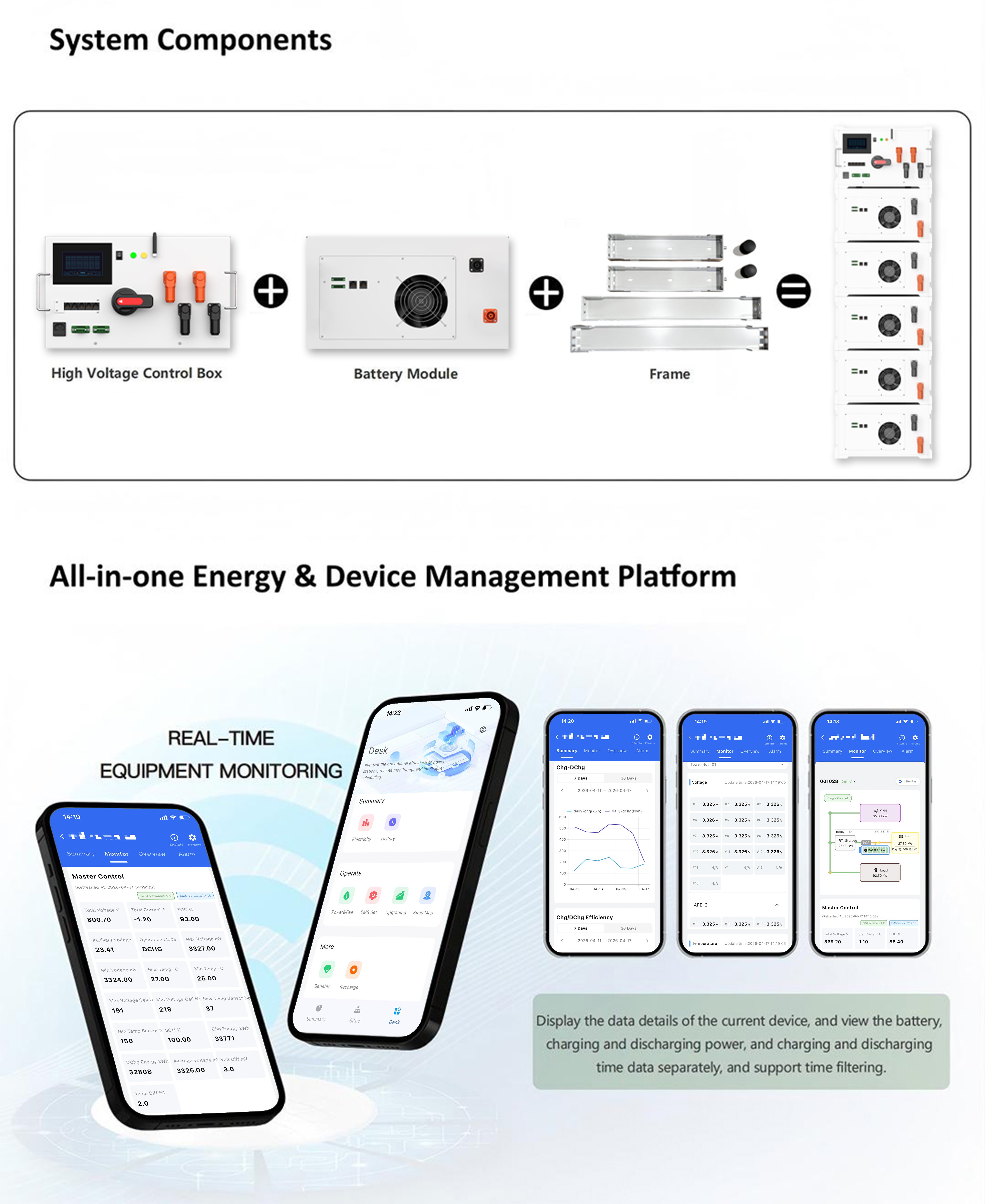
Depending on the supplied version, monitoring can include a 4.3-inch master LCD and WiFi access through CloudESS. Confirm available module and cell data, temperature readings, balancing status, history and alarms in the ordered hardware and firmware documentation. Mobile-platform support, efficiency statistics and cloud multi-site functions require specific confirmation.
Does JKESS provide installation support for B2B customers?
Request the current model-specific wiring diagrams, installation manual and commissioning guide from JKESS when specifying the project. Confirm remote support scope and availability in the quotation, especially for larger orders. Standardized kits and harnesses simplify assembly, while qualified installation and project-level verification remain necessary.
Ready to Scale Your C&I Energy Storage Project?
Start with a 64kWh pilot configuration and expand to 256kWh as your load data validates the business case. Our engineering team can help you plan the stack topology, wiring sequence, and commissioning process.
Request a Custom Quote→