
 EN
EN
JKESS Engineering Insights
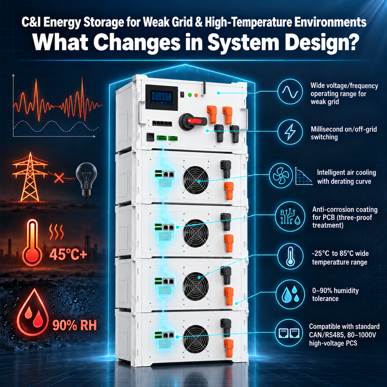
Get a Quote→C&I Energy Storage for Weak Grid & High-Temperature Environments: What Changes in System Design?
A standard BESS selected for a stable grid and a temperate climate can fall short at a hot, humid, or weak-grid site. Here are the 5 design changes that separate a viable project from avoidable downtime and warranty disputes.
Key Takeaways
- Weak grids and tropical climates change the design constraints. They are fundamental project inputs, not a minor adjustment to a standard BESS specification.
- Standard BESS design assumptions can fail on a weak grid: stable voltage, steady frequency, and controlled ambient conditions cannot be taken for granted.
- Heat and humidity act through different mechanisms. Heat accelerates cell aging and can increase imbalance; moisture, condensation, and salt contamination threaten insulation, connectors, and communication reliability.
- Five changes matter: suitable AC voltage/frequency windows, thermal derating, three-proof electronics protection, a validated millisecond transfer design where required, and active balancing to manage cell SOC divergence.
- Match JKESS components to the complete system. The BMU-H5-16 lists up to 2A active balancing and a -25°C ~ 85°C electronics operating range. Kit-level temperature sensing, site humidity, altitude, battery limits, and PCS requirements must be assessed together.
01 / The design problem
Why Standard BESS Designs Fail in Weak Grid & Tropical Climates
When specifying a commercial and industrial battery energy storage system (C&I BESS), many buyers start with the assumptions used for a stable utility supply. At a weak-grid site, those assumptions need to be tested against measured voltage, frequency, outage duration, and fault conditions. For example, a design study may need to evaluate voltage excursions of ±15% or more and frequency deviations exceeding ±1Hz. These are project scenarios to investigate, not universal values for Southeast Asia, the Middle East, Africa, or Latin America.
The local climate adds another set of constraints. A tropical facility may experience ambient temperatures above 35°C and sustained relative humidity above 80%; a desert site may instead combine extreme heat with dust. Coastal projects can face salt contamination. Cooling capacity, insulation coordination, enclosure protection, and communication routing must address the conditions actually present, including condensation during daily temperature changes.
The result of a mismatch can be thermal power limiting, lost usable capacity, repeated shutdowns, communication faults, or insulation alarms. A ten-year project objective is not evidence of ten-year performance at every site, and neither a 3–5 year failure prediction nor a fixed lifetime extension can be inferred from climate alone. The practical question is whether the selected cells, BMS, PCS, cooling system, and written warranty all cover the intended duty cycle and operating environment.
02 / Compare the assumptions
Standard BESS Design vs Weak-Grid & High-Temperature Optimized Design
Illustrative procurement comparison. Baseline assumptions below are examples of an underspecified project, not limits shared by every standard BESS.
| Standard BESS Stable grid, temperate assumptions |
Weak-Grid & High-Temp Optimized |
|---|---|
| Standard assumption Voltage windowAC selection based only on a nominal ±10% example window. | Optimized design Site-matched AC windowAssess ±15% or larger excursions where recorded; specify PCS operating and ride-through behavior within local grid rules. |
| Standard assumption Frequency stabilityAssume 50/60Hz stays within an example ±0.5Hz band. | Optimized design Frequency responseCoordinate permissible frequency range, protection, and recovery using site data. |
| Standard assumption Unverified transferRely on an external switch without checking load interruption. | Optimized design Validated backup transferSpecify a millisecond transfer target where needed and verify the complete PCS, switchgear, and load response. |
| Standard assumption Temperate cooling basisSize the installation using a 25°C rating alone. | Optimized design Hot-site deratingEvaluate 45°C+ conditions, cooling auxiliaries, airflow, and temperature-driven power limits. |
| Standard assumption Unprotected electronicsNo project requirement for moisture or contamination protection. | Optimized design Three-proof treatmentSpecify conformal coating, suitable connectors, and controls for moisture, salt contamination, and fungal growth. |
| Standard assumption Limited balancing capacityDepend on factory matching and low-current passive balancing. | Optimized design 2A active balancingUse charge transfer to manage SOC divergence within the approved balancing conditions. |
| Standard assumption Basic communication routingNo additional review of shielding, grounding, or interference. | Optimized design Robust communicationCoordinate cable separation, shielding, isolation, termination, and fault handling. |
| Standard assumption Unchecked warranty envelopeAssume a rating at 25°C ±5°C also covers the site's extremes. | Optimized design Explicit operating conditionsAgree the whole-system temperature, humidity, duty cycle, and derating terms in writing. |
| Standard assumption Geography as a proxyTreat a stable-grid installation as a universal template. | Optimized design Site-specific applicationEvaluate tropical, desert, coastal, remote, and island projects on their measured conditions. |
| Standard assumption Unsubstantiated service lifeA nominal ten-year plan with no hot-site performance evidence. | Optimized design Documented lifetime basisValidate the project-life target with cell aging data, operating limits, maintenance, and agreed warranty coverage. |
03 / Five system-level changes
The 5 Design Changes That Make a BESS Viable in Weak Grid & High-Temp Environments
-
Wide Voltage and Frequency Windows
Separate the AC grid window from the DC battery window. The PCS determines how the system responds to grid voltage and frequency disturbances. A BMS rated for 80–1000V DC does not, by itself, establish AC ride-through capability or permission to remain connected outside local protection limits.
For sites with measured voltage fluctuations around ±15% or frequency variations above ±1Hz, specify the permissible PCS range and the response to disturbances. Check the battery string's minimum and maximum voltage across SOC and temperature against the PCS DC input range. The JKESS HV master platform provides CAN/RS485 interfaces for integration, but message definitions, firmware behavior, and fault recovery still need to be agreed.
Validate sampling accuracy and communication at both voltage extremes and during transients. Increasing an operating window must not defeat overvoltage, undervoltage, anti-islanding, or other required protection.
-
Thermal Management with Explicit Derating
Size for the hottest credible operating condition. A 25°C power rating is only one point on a thermal performance curve. At 45°C or above, evaluate cell heat generation, PCS losses, enclosure solar gain, filter loading, fan performance, and the power used by cooling equipment.
The JKESS master-and-slave kit specification describes controllable fan cooling and an 8-channel NTC sensing configuration, with a -30~105°C measurement range and ±2°C stated precision. Use temperature measurements from representative hot spots to trigger fan control, charging/discharging limits, and protective shutdowns. Sensor coverage and response time matter as much as the channel count.
The BMU electronics range of -25°C ~ 85°C is not a battery-cell charging or discharging allowance. The HV-BC250 product page separately lists -20°C to +65°C operation. The complete BESS must respect the most restrictive installed component and the selected cell limits. Ventilation alone cannot cool cells below ambient temperature; a site may require conditioned cooling.
-
Three-Proof Protection: Moisture, Salt, and Mold
Treat humidity, condensation, and contamination as separate design inputs. “Three-proof” treatment commonly refers to conformal coating intended to improve resistance to moisture, salt contamination, and fungal growth. The coating system, coverage, process control, and environmental qualification determine the protection actually achieved.
For a tropical or coastal project, specify the required board treatment with JKESS and obtain confirmation for the supplied configuration. A RAL9003 signal-white enclosure finish does not establish PCB coating, enclosure sealing, or salt-spray resistance. Connectors, cable glands, insulation distances, and grounding need their own assessment.
Use an enclosure and moisture-control strategy appropriate to the site. Consider condensation during cooling or shutdown, drainage, and maintenance access. Coating supports environmental protection; it does not replace insulation coordination, an appropriate enclosure, or project-specific environmental testing.
-
Millisecond Switchover, Verified at the Load
Define the acceptable interruption before choosing the architecture. A production line, contactor-controlled motor, cold store, and server load can have different interruption and restart tolerances. The required transfer time must be a measurable acceptance criterion.
JKESS CAN/RS485 interfaces support coordination with a suitably specified PCS. However, a communication interface or a millisecond command does not prove millisecond backup transfer. The total interruption includes grid-fault detection, controls, isolation or switching, PCS mode transition, and voltage recovery at the load.
Where millisecond backup is required, select the appropriate PCS and transfer equipment, maintain the necessary battery reserve, and test the integrated system at representative load and SOC. Include motor starting, overload, repeated outages, and reconnection behavior in the acceptance test.
-
Active Balancing to Maintain Cell SOC Consistency
Active balancing addresses charge imbalance; cooling addresses temperature. Differences in self-discharge, capacity, and temperature can make cells reach their voltage limits at different times. Charge transfer can reduce the resulting SOC divergence and improve access to otherwise stranded pack capacity.
The BMU-H5-16 product specification lists up to 2A active balancing per channel. Active balancing transfers energy between cells, while passive balancing dissipates excess charge as heat. The permitted SOC and voltage range, current, temperature limits, and simultaneous channel behavior depend on the controller configuration; continuous 2A operation across all conditions should not be assumed.
Illustrative charge-transfer calculation
Charge difference = 314 Ah × 0.5% = 1.57 Ah
Ideal balancing time = 1.57 Ah ÷ 2 A
= 0.785 h ≈ 47 minutes
This is an ideal calculation for transferring 1.57Ah at a constant net 2A. Actual balancing time depends on the topology, effective current, operating thresholds, conversion losses, and the number of cells requiring correction. Balancing does not restore lost cell capacity or guarantee a cell temperature spread below 3°C or a 15%–20% lifetime increase.
04 / A sizing example
Thermal Derating: What Changes When Ambient Temperature Hits 45°C
Thermal derating reduces the permitted power as temperature rises. For an initial sizing exercise, multiply the reference power by a temperature-dependent factor, then check battery, PCS, enclosure, and auxiliary-power limits together.
Simplified discharge-power calculation
Available Discharge Power = Rated Power × Derating Factor (T_ambient)
| Ambient temperature | Example derating factor | Output from a 100kW rating |
|---|---|---|
| 25°C | 1.00 | 100 kW |
| 35°C | 0.95 | 95 kW |
| 45°C | 0.85 | 85 kW |
| 55°C | 0.70 | 70 kW |
Use extreme site temperature, not the annual average. In this example, delivering 100kW at 45°C would require at least 100 ÷ 0.85 ≈ 117.6kW of reference capacity before other limits or cooling auxiliaries. Obtain the selected system's actual charge and discharge derating curves; an electronics temperature limit does not establish available battery power.
The approved design must also address minimum-temperature charging limits, equipment aging, airflow obstruction, and the energy reserve needed through the longest planned outage.
05 / Match hardware to requirements
How JKESS HV BESS Meets Weak-Grid & High-Temp Requirements
Use the JKESS HV master and slave-box platform as the battery-management foundation, then qualify the complete installation for the site. The configurations discussed here use the HV-BC250 or HV-BC150-100A master, HV-B6U slave battery box kits, and the BMU-H5-16 active balance unit. Kits are supplied without battery cells; final performance depends on the assembled system.
| Design requirement | JKESS parameter / scope | Value for B2B buyers |
|---|---|---|
| DC voltage range | 80–1000V DC; 64S–256S architecture in the HV-BC250 specification. | Supports battery-string selection against a PCS DC window; AC grid performance remains a PCS requirement. |
| Temperature range | BMU-H5-16: -25°C ~ 85°C. HV-BC250: -20°C to +65°C. | Identify the limiting component and cell temperature envelope before approving hot-site operation. |
| Humidity tolerance | 0–90% RH is the project target in this design brief, not a verified whole-system rating. Standalone BMU listing: 5–95% RH, non-condensing. | Specify condensation control and obtain the cabinet, connector, and complete-system humidity limits. |
| Altitude | ≤2000m in the master-and-slave kit specification. | Check site elevation and any additional cooling or insulation derating. |
| Active balancing | BMU-H5-16, up to 2A active balancing; kit-level cell voltage precision ±0.005V. | Manage cell SOC divergence with a defined balancing strategy and accurate cell monitoring. |
| Temperature monitoring | 8-channel NTC configuration in the kit listing; -30~105°C / ±2°C. Standalone BMU listing specifies 16 NTC channels. | Confirm the installed harness and sensor coverage; use feedback for thermal controls and protection. |
| Cooling | Intelligent air cooling / controllable fan in the slave kit. | Coordinate fan operation with temperature data; assess whether the site needs additional conditioned cooling. |
| Communication | CAN / RS485 at the master; daisy-chain architecture with the specified slave interface. | Agree message mapping, cable design, timeouts, and PCS integration before commissioning. |
| System expansion | 4–16 slave boxes; approximately 64–256kWh project class, dependent on cell selection. | Scale voltage and nominal energy with module count; verify PCS voltage, mechanical support, and expansion policy. |
| Compliance documentation | Kit page references GB34131-2017; manufacturer lists CE, RoHS, and FCC for relevant products. | Obtain model-specific documents and check the applicable editions and local requirements; these labels do not establish complete-system grid approval. |
Capacity is a calculation, not a box-count guarantee. With 16 series LFP cells per box at 3.2V nominal and 314Ah, each box has about 16.08kWh nominal energy. Four to sixteen boxes therefore provide about 64.3–257.2kWh nominal, before usable SOC limits, losses, aging, and reserve requirements. “64–256kWh” describes the approximate project class.
Manufacturer references: HV-BC250 master specifications; master-and-slave kit specifications; BMU-H5-16 specifications; HV slave 6U kits. Reviewed October 10, 2026.
Published pages describe different configurations and include inconsistent sensor and balancing figures. The table identifies the scope of each selected value. Use an agreed model-specific datasheet and bill of materials for procurement, integration, and acceptance.
06 / Application scenarios
Where Weak-Grid & High-Temp BESS Is Deployed
These are application scenarios for site-specific system design; backup continuity and financial results depend on the selected equipment, load profile, tariffs, and operating strategy.
Southeast Asia / Manufacturing
Food, Packaging, and Light Industry
Frequent outages can stop production and increase restart losses. Storage can combine backup reserve with time-of-use operation, provided the transfer system meets the line's interruption tolerance and the tariff supports the operating strategy.
Middle East / Commercial
Hotels, Supermarkets, and Offices
Air-conditioning demand can coincide with 45°C+ outdoor conditions. Evaluate demand reduction using the power actually available in the heat, while retaining sufficient energy for essential loads during an outage.
Africa / Remote Operations
Mining and Agricultural Processing
Remote facilities can use PV, storage, and dispatchable generation together. Include motor starting, dust, maintenance access, fuel logistics, and stable islanded operation when planning weak-grid or off-grid supply.
Islands / Hybrid Microgrids
Communities and Tourism Resorts
PV and storage can reduce generator run time where the dispatch strategy permits. Assess salt exposure, variable renewable output, reserve margins, and black-start capability; active balancing supports charge consistency within the battery string.
Cold Chain / Logistics
Cold Stores and Distribution Warehouses
High outdoor temperatures increase refrigeration demand. Size for compressor starting, the essential cooling load, the allowed temperature rise during interruptions, and backup duration before committing energy to peak reduction.
Telecom / Critical Loads
Base Stations and Data Facilities
Match the storage voltage to the site's AC or DC conversion architecture and continuity requirements. Higher distribution voltage reduces current at a given power, but conversion losses, standby demand, and transfer performance still need evaluation.
07 / Direct answers
Frequently Asked Questions
Why do standard BESS designs fail in weak grid environments?
A BESS can underperform when its PCS operating window, protection settings, or backup architecture do not match measured grid disturbances. Voltage excursions of ±15% or more and frequency deviations beyond ±1Hz are possible design scenarios to investigate, not universal regional limits. Validate the AC response separately from the battery's DC voltage range and coordinate all settings with the applicable grid requirements.
How does high ambient temperature affect BESS performance?
High temperature accelerates cell aging and can reduce usable power through thermal derating. In the illustrative table here, a 100kW rating multiplied by a 0.85 factor gives 85kW at 45°C; the actual value requires the selected system's curve. The BMU-H5-16 lists -25°C to +85°C electronics operation, while the HV-BC250 lists -20°C to +65°C. Neither range establishes battery-cell operating limits.
What is thermal derating and why does it matter for my project?
Thermal derating limits permitted charge or discharge power as temperature rises to keep equipment within its operating limits. The 0.85 factor at 45°C used in this article is an example, not a universal or verified JKESS curve. Size from the site's extreme operating conditions and obtain the complete system's power-versus-temperature data, including cooling auxiliaries.
How does active balancing help in high-temperature environments?
Temperature and cell differences can contribute to SOC divergence, causing individual cells to reach voltage limits early. The BMU-H5-16 lists up to 2A active balancing, transferring charge within the battery rather than relying only on resistive discharge. For 314Ah cells, moving a 0.5% charge difference at a constant net 2A takes approximately 47 minutes in an ideal calculation; actual time depends on operating conditions. Balancing does not replace cooling or guarantee a particular lifetime increase.
What does “three-proof” treatment mean for BESS electronics?
Three-proof treatment commonly refers to conformal coating intended to improve resistance to moisture, salt contamination, and fungal growth. Protection depends on the material, application quality, coverage, and environmental qualification. It does not replace an appropriate enclosure or condensation control, and the treatment must be confirmed for the supplied product.
Can JKESS BESS switch between grid-connected and off-grid modes quickly?
Fast transfer is a system-level capability that depends on the PCS, transfer equipment, controls, and load. JKESS CAN/RS485 interfaces support integration, but communication capability alone does not establish interruption time. Set the required millisecond target and validate it at the load under representative operating conditions.
What voltage range does the JKESS HV BESS support?
The HV master specification lists an 80–1000V DC range and a 64S–256S architecture. At an assumed 3.2V nominal per LFP cell, 64S and 256S correspond to 204.8V and 819.2V nominal. Check the full battery voltage range against the selected PCS DC input limits; this DC rating does not establish AC grid ride-through performance.
How many slave boxes can be stacked in a weak-grid installation?
The JKESS master-and-slave kit listing supports 4–16 slave battery boxes per master, subject to the approved configuration and mechanical installation. The HV-BC250 and HV-BC150-100A options must be matched to the required current and PCS voltage window. With 16S, 3.2V, 314Ah cells per box, nominal energy is approximately 64.3–257.2kWh across that range; usable energy is lower and project-specific. Expansion must follow the approved cell-matching and commissioning procedure.
Does high humidity affect BESS warranty coverage?
Humidity and condensation conditions can affect whether an installation is within its specified operating envelope and written warranty terms. The 0–90% RH figure in the project brief is not verified here as a whole-system rating; the standalone BMU page lists 5–95% RH, non-condensing. Confirm the complete installation's limits and any required moisture controls in the supply agreement.
What certifications should I look for in a BESS for weak-grid regions?
Ask for model-specific documentation covering the battery, BMS, PCS, electrical safety, EMC, and the applicable local grid-connection requirements. JKESS's kit page references GB34131-2017, and manufacturer pages list CE, RoHS, and FCC for relevant products. Verify document scope, applicable editions, and project requirements; these references alone do not demonstrate approval of a complete BESS for a particular grid.
Planning a BESS for a Weak-Grid or High-Temperature Site?
Share your site conditions — voltage fluctuations, ambient temperature profile, humidity levels — with our engineering team. We'll help you map those constraints to a modular HV BESS configuration that meets your project's operational and warranty requirements.
Request a Custom Quote→