
 EN
HV BMS Fault Codes Decoded: Voltage Imbalance, Temperature Alarms, and Communication Loss — A Field Troubleshooting Flow
Three alarm categories cause most field callbacks. Here is the three-tier diagnostic framework — alarm type → data distribution → root cause — with measurable thresholds you can apply on-site, not just “check the wiring.”
Key Takeaways
- An alarm code identifies a symptom, not the root cause. A voltage imbalance reading can involve cells, sampling wiring, or balancing; cooling and communication faults can also affect the data used for diagnosis.
- Voltage imbalance, temperature alarms, and communication loss account for much of the troubleshooting work during commissioning and maintenance.
- Use a three-tier diagnostic framework: alarm type → data distribution → root cause. Identify the alarm, examine cell-level patterns, then isolate wiring, sensors, cells, or communication configuration.
- Every diagnostic tier needs measurable thresholds and recorded test conditions, rather than a judgment that something “feels wrong.”
- Screening references include insulation resistance ≥1 MΩ at 1,000 VDC, cell voltage difference ≤50 mV, and handshake response <1 s. Confirm applicability and the approved test procedure in the manual for the delivered system.
Why “Check the Wiring” Is Not a Troubleshooting Answer
An energy storage BMS can generate many alarm codes. When a commissioning engineer is standing in front of a master display showing “voltage imbalance” at two in the morning, a list of codes is not enough. What they need is a reasoning path from the alarm category to the underlying cause.
The same alarm can have several causes. Voltage imbalance may reflect differences in cell capacity, a poor sampling-harness connection, insufficient terminal torque, or active balancing that has not started. A temperature alarm may signal a real thermal problem, a detached NTC probe, or a stopped cooling fan. Communication loss may involve missing CAN bus termination or a baud-rate mismatch.
If the troubleshooting method is “try replacing a board first,” site time and spare-parts costs can escalate. This guide presents a three-tier diagnostic framework that helps engineers narrow the fault domain before arriving on-site. Numeric fault-code meanings remain specific to the installed model and firmware.
Three Alarm Categories, Their Root Causes, and the Data That Distinguishes Them
Use the data signatures below to prioritize checks. A pattern is a diagnostic clue; confirm the cause before changing hardware or protection settings.
| Alarm Category | Common Root Causes | Distinguishing Data Signature | First Diagnostic Step |
|---|---|---|---|
| Voltage Imbalance | Cell capacity drift / Sampling harness contact resistance / Terminal torque / Active balancing not running |
Specific or adjacent channels repeatedly affected → inspect the shared sampling path and connections. The same cell diverges under comparable conditions → investigate cell behavior. A migrating pattern or uniform drift is not conclusive; verify measurement references and balancing status. |
Check whether the imbalanced channels are physically adjacent or scattered; compare the time trend and operating conditions. |
| Temperature Alarm | Actual thermal event / NTC probe detached / Cooling fan stopped / Ambient temperature exceeded derating curve |
One extreme NTC reading with normal adjacent readings → probe, connector, or a localized hot spot. All NTCs rise together → investigate thermal conditions, airflow, and fan operation. |
Compare the flagged NTC with adjacent sensors on the same module, then independently verify temperature under the site procedure. |
| Communication Loss | Termination incorrect / Baud rate mismatch / Shielded cable ground loop / Address collision / Node power or harness fault |
Loss after adding slaves → investigate topology, cable length, capacity, power, and configuration; eight is not a universal limit. Intermittent loss under load → investigate EMI, grounding, or power stability. One slave disappears → inspect its power, harness, and address. |
Identify the affected bus type. For high-speed CAN, verify both physical bus ends and existing termination against the wiring diagram before replacing any board. |
Reactive Replacement vs Structured Diagnosis: A Side-by-Side Comparison
- TIER 01Alarm typeIdentify the symptom and affected node.
- TIER 02Data distributionCompare adjacency, timing, and load.
- TIER 03Root causeConfirm with measured evidence.
| Reactive Approach (Common) | Structured Diagnosis (JKESS Framework) |
|---|---|
| See the alarm code, swap the BMS board | Read alarm type, then check the data distribution before touching hardware |
| Test each component randomly | Narrow the fault domain using channel adjacency and time trend |
| Wait for spare parts to arrive | Confirm root cause with applicable measurable thresholds (≤50 mV, ≥1 MΩ, <1 s) and independent checks |
| If the fault moves, start over | Each diagnostic step narrows the next step |
| High downtime and parts cost | Reduce unnecessary truck rolls and spare board consumption |
| No documentation of what actually failed | Fault signature recorded for future preventive maintenance |
Measurable Thresholds You Can Apply On-Site
| Check Item | JKESS Engineering ThresholdConfirm against the delivered-system manual | What the Check Helps Assess |
|---|---|---|
| Cell voltage difference (max–min) during scheduled downtime |
≤50 mV At the defined rest condition, state of charge, and temperature |
Screens for voltage spread. A passing value alone does not rule out capacity loss or sampling error. |
| Insulation resistance between power terminals and chassis ground |
≥1 MΩ at 1,000 VDC Only where the approved system test procedure specifies these values |
Checks the specified insulation path for leakage that may involve cable damage, moisture, or insulation failure. It does not certify the entire system. |
| Slave-to-master handshake response time |
<1 second With a defined start event and confirmed node and firmware configuration |
Checks communication responsiveness. A fast handshake alone does not rule out intermittent errors or incorrect termination. |
| Active balancing current verification |
Up to 2A on BMU-H5-16 Maximum capability; actual current depends on enable conditions and operating state |
Confirms balancing activity when commanded and eligible. Zero current can be normal when activation conditions are not met. |
| Temperature sensor deviation vs adjacent NTC |
Within ±2°C Comparison target only under equivalent thermal conditions |
Flags inconsistent readings for verification. Sensor accuracy and real thermal gradients mean ±2°C is not a universal adjacent-sensor fault limit. |
| LED status on slave BMU |
Green steady: normal Flashing or off: diagnostic required, if this matches the installed model’s LED legend |
Provides an initial power or communication clue. Verify the model-specific LED pattern; it is not proof of a healthy slave. |
JKESS HV BESS Components Designed for Field Diagnosability
| Component | Model | Diagnostic Feature | Product Link |
|---|---|---|---|
| 200A HV Master Box | HV-BC250 | Built-in BCU with CAN/RS485/daisy-chain interfaces; front-panel LED for run/fault status | View Details → |
| 100A HV Master Box | HV-BC150-100A | Same diagnostic architecture for smaller clusters; LED indicators and LCD support | View Details → |
| 6U Slave Battery Box | HV-B6U | BMU-H5-16 with per-cell voltage (±0.005V) and 8 NTC channels in the referenced kit configuration; LED status per box | View Details → |
| 4U Slave Battery Box | HV Slave 4U | Compact 19-inch slave box with the same BMU platform | View Details → |
| Modular Stacked System | HV BMS Master + Slave Kits | 1 master + 4–16 slaves; diagnostic data accessible via LCD and the documented CAN interface | View Details → |
3 Mistakes That Turn a 30-Minute Fix into a 3-Day Callback
Mistake 1: Replacing the BMS as Soon as Voltage Imbalance Appears
A poor sampling connection or insufficient terminal torque can also appear as voltage imbalance. Inspect the channel distribution and verify the readings before deciding whether hardware intervention is necessary. Carry out physical checks only under the approved isolation procedure.
Mistake 2: Treating Every Temperature Alarm as Proof of Thermal Runaway
An extreme reading from one NTC while adjacent sensors remain normal can indicate a probe or connector problem, but a localized hot spot is also possible. Cross-check sensors and independently verify temperature. Keep protection active; follow the site emergency procedure if abnormal heating, smoke, or venting is suspected.
Mistake 3: Checking Only the Cable When Communication Is Lost
Incorrect termination, a baud-rate mismatch, an address conflict, or a shield grounding problem can all cause communication loss. Narrow the problem by node count, timing, and affected node. Identify the bus type before applying a termination or configuration change.
Frequently Asked Questions
What causes a voltage imbalance alarm on an HV BMS?
Voltage imbalance can be caused by cell capacity drift, sampling harness contact resistance, insufficient terminal torque, or active balancing not running. Start by checking whether the flagged channels are physically adjacent or scattered, then compare their time trends at similar current, temperature, and state of charge. Adjacent channels can point to shared wiring; recurring divergence of the same cell can indicate a cell issue. A moving pattern or uniform drift alone does not prove cell degradation or disabled balancing. Confirm with independent measurements under the approved service procedure.
How do I distinguish a real thermal event from a faulty temperature sensor?
Compare the flagged NTC reading with adjacent NTCs on the same module. One extreme reading with normal neighbors may indicate a probe or connector fault, but it can also reflect a localized hot spot. Correlated rises across sensors warrant investigation of actual thermal conditions, airflow, and fan operation. Keep protections active and confirm the temperature independently under the site procedure before treating the alarm as a sensor fault.
Why does the communication drop only when the number of slave boxes exceeds 8?
There is no universal eight-slave CAN threshold. Loss after expansion can expose topology, cable length, power, addressing, controller capacity, or termination problems. First identify whether the affected segment is CAN, RS485, or the BMU daisy chain. For a high-speed CAN segment, verify termination at both physical bus ends against the wiring diagram, accounting for built-in termination. Do not add a CAN resistor to an isoSPI or other non-CAN port. Verify the actual segment and configuration before replacing hardware.
What thresholds should I use for insulation resistance and cell voltage difference?
This guide uses ≥1 MΩ at 1,000 VDC and ≤50 mV as project screening references, subject to the approved manual for the delivered system. They are not universal acceptance or alarm limits. Cell voltage spread must be assessed at a defined state of charge, temperature, and rest condition. Only qualified personnel may perform insulation testing, using the specified isolation, disconnection, test voltage, and discharge procedure; never apply a test voltage to connected electronics unless the manufacturer explicitly permits it.
What does the LED status on the slave BMU indicate?
Where confirmed by the installed model’s LED legend, green steady indicates normal operation, while flashing or off requires diagnosis. LED meanings can vary by hardware and firmware revision. Treat the LED as a first-level indicator, not a root-cause diagnosis; check power, communication, and the relevant status log using the three-tier framework.
Can I use a generic CAN analyzer to read JKESS BMS data?
A compatible, appropriately isolated CAN analyzer can read the documented CAN segment if the pinout, voltage levels, and baud rate match the installed system. Supported configurations may use 250k or 500k. Protocol mapping is needed to interpret CAN identifiers, payloads, scaling, and alarms. RS485 requires an appropriate RS485 interface, and the BMU daisy chain may require a different diagnostic interface.
How do I verify that active balancing is actually running?
Check the enable state, activation conditions, and balancing-current telemetry or the approved service measurement for the BMU-H5-16. Up to 2A is a maximum capability, not a current that must always be present. Compare voltage spread at equivalent rest conditions, state of charge, and temperature before and after balancing. If an enabled, eligible channel shows no activity, investigate configuration, wiring, and the balancing circuit under the approved procedure.
What should I record after resolving a fault?
Record the alarm type, exact code, hardware and firmware revision, the observed data signature (channel adjacency, time trend, and NTC comparison), test conditions, the threshold exceeded, and the corrective action taken. Include before-and-after logs and the verification result. This fault signature supports preventive maintenance and diagnosis of similar issues at other sites.
Does JKESS provide field troubleshooting support?
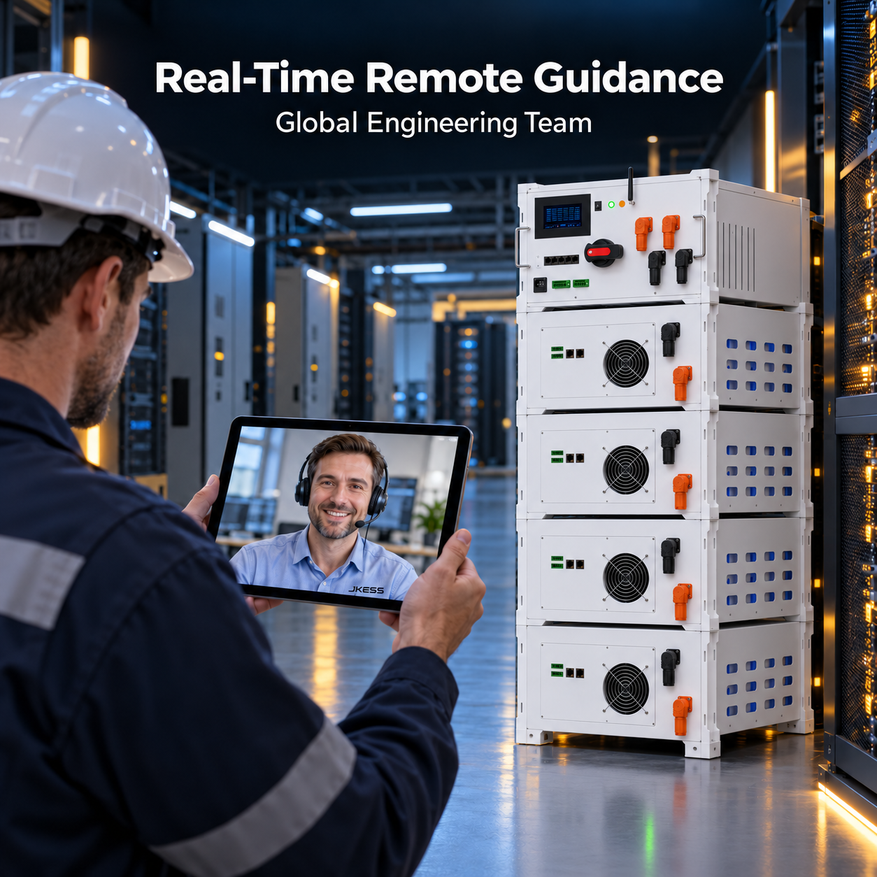
JKESS provides technical documentation including installation manuals, wiring diagrams, and commissioning guides. Request the revision and applicable thresholds for your delivered system. For B2B projects, remote technical support can be arranged to assist with fault diagnosis and configuration review.
What is the most common cause of a “communication loss” alarm in a new HV BESS installation?
Common commissioning checks include a baud-rate mismatch between the master and PCS, incorrect termination on a CAN segment, address conflicts, and wiring or power faults. There is no universal ranking without site failure data. In an operating system, investigate load-related interference, grounding, connector damage, and power stability as well. Identify the affected communication segment before applying a bus-specific fix.
Facing an HV BMS Alarm You Cannot Reproduce?
Share the alarm type, data logs, and site conditions with our engineering team. We’ll help you narrow the fault domain using the three-tier diagnostic framework — before you dispatch a technician or replace a board.
Request a Custom Quote →