
 EN
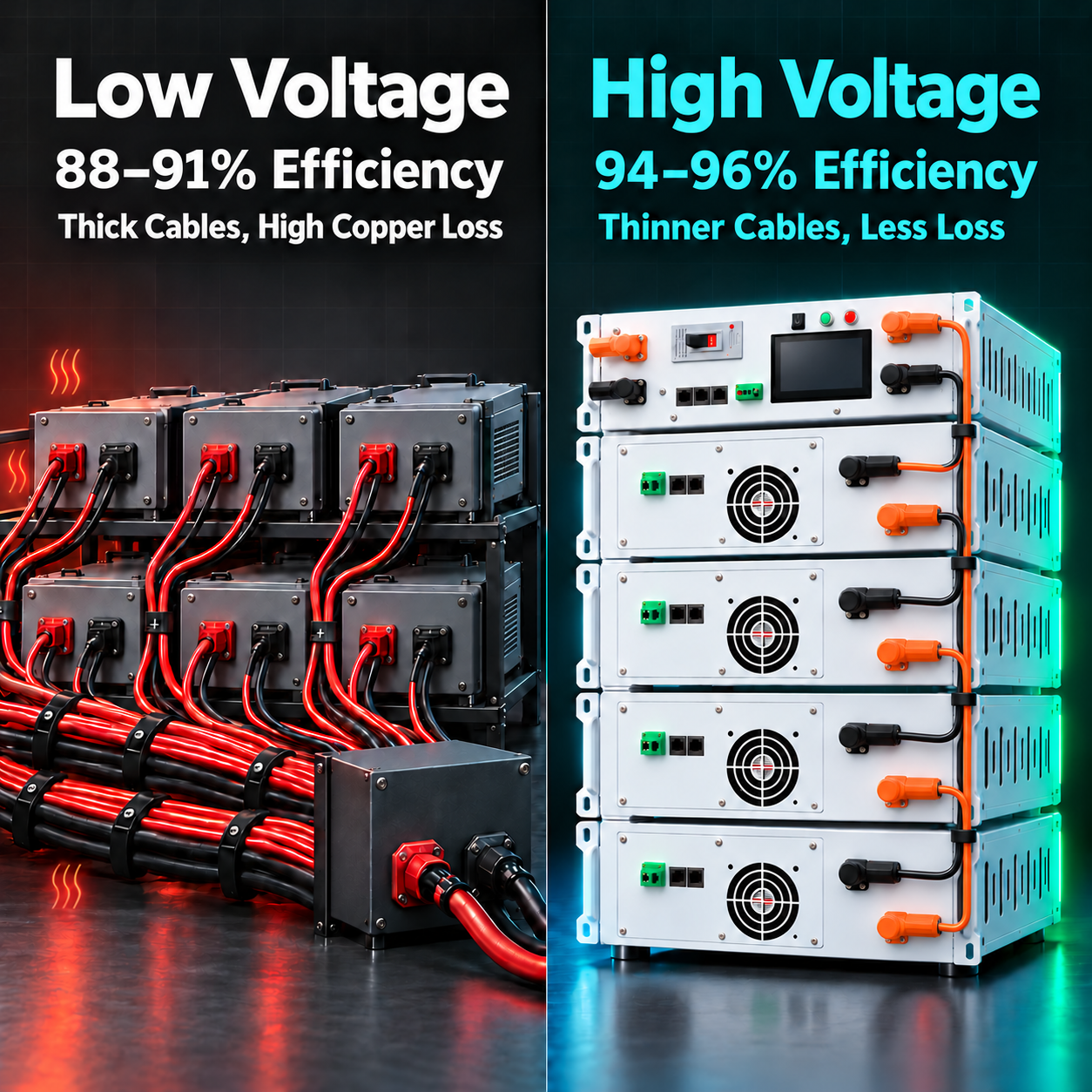
Upgrading from LV to HV Battery Storage: What Changes in Efficiency, Wiring, and Inverter Compatibility
A 48V system hits a power ceiling faster than most C&I projects expect. Here is the 5-point upgrade checklist — DC voltage window, inverter compatibility, wiring loss, BMS architecture, and safety clearance — before you commit to a high-voltage cluster.
Key Takeaways
- Current is the main scaling constraint. As power demand increases, a 48V system needs rapidly increasing current. Cable losses, connection heating, and cooling demand can become major efficiency bottlenecks.
- An LV-to-HV upgrade is a system redesign. The 5-point upgrade checklist covers the DC voltage window, inverter/BMS compatibility, cables and protection, BMS architecture, and insulation clearances. Hardware rated for 80–1000V must still be matched to a specific battery configuration.
- Higher voltage means lower current at equal power. At 144–192V, current is one-third to one-quarter of that at 48V. At 400V, it is about 12%: 50kW requires 125A instead of approximately 1,042A, before conversion losses.
- Verify the inverter first. Its battery DC input window must cover the full cluster operating range, and its BMS protocol must map correctly to the HV master. Matching connector types alone is insufficient.
- Build around a matched hardware platform. JKESS 100A/200A HV master boxes and 4U/6U slave kits provide a modular foundation for new HV projects and engineered LV-to-HV upgrades.
Why 48V Systems Hit a Power Ceiling
48V low-voltage battery storage is common in residential and small commercial applications. As project demand rises to tens or hundreds of kilowatts, the practical limits of a low-voltage architecture become increasingly important. The ceiling is set by the inverter, conductors, connections, protection, and installation conditions; there is no single power threshold for every 48V system.
The central issue is current. DC power equals voltage multiplied by current. Delivering 50kW at 48V requires approximately 1,042A, while the same DC power at 400V requires 125A. Higher current demands larger conductors and connections, and increases resistive heating for a given circuit resistance. Cable losses and cooling loads can erode system efficiency.P = V × I · I = P / V · Cable loss = I²R
When an owner wants more capacity or higher PV self-consumption, the choice is often to parallel more 48V batteries or move to a high-voltage architecture. Adding parallel capacity does not, by itself, increase current at a fixed total power; increasing power does. The decision therefore requires more than a battery quotation: assess the five system-level changes below.
48V LV vs High-Voltage BESS: A System-Level Comparison
| Dimension | 48V low-voltage system | High-voltage system (80–1000V hardware range) |
|---|---|---|
| Current at the same power | High: approximately 1,042A at 50kW / 48V. | Lower: 125A at 50kW / 400V. |
| Cables & copper losses | Higher current calls for larger conductors, larger connections, and more routing space. | Lower current can reduce conductor size, copper losses, and routing space; HV insulation is still required. |
| System efficiency | 88–91% RTE in the illustrative comparison below; not a universal LV rating. | 94–96% RTE in the illustrative comparison below; not a universal HV rating. |
| Expansion method | Parallel additional 48V modules. Higher power increases total current; adding capacity alone does not. | Series modules raise voltage and energy; approved parallel HV clusters add capacity at the same voltage. |
| Inverter compatibility | Requires an inverter designed for the selected low-voltage battery range and protocol. | The inverter’s battery DC window must cover the cluster’s actual minimum-to-maximum voltage. |
| BMS architecture | Often an integrated module BMS, with coordination across parallel modules where required. | Typically a master with multiple slave BMUs, coordinated protection, and insulation monitoring as required. |
| Safety design | Lower voltage, but substantial fault current, connection heating, and fire risks remain. | Higher shock and arcing risks call for rated insulation, pre-charge, protection, and interlocks as applicable. |
| Typical applications | Residential storage, small backup systems, and lower-power applications. | C&I storage, grid-side projects, and higher-power charging and discharging. |
Efficiency comparison: The 88–91% and 94–96% figures are illustrative planning ranges, not measured results or guarantees for all LV and HV systems. Compare round-trip efficiency at the same AC or DC measurement boundary, power, temperature, state-of-charge window, and auxiliary-load conditions. Lower cable loss alone does not establish whole-system efficiency.
The 5-Point Upgrade Checklist Before You Switch to HV
-
Confirm the existing inverter’s DC input window
The selected battery cluster’s full voltage range, from its lowest permitted discharge voltage to its highest charge voltage, must fit within the inverter/PCS battery DC window. Check startup voltage, current limits, and power capability throughout that range. A master rated for 80–1000V does not mean every battery cluster operates across that entire range.
If the existing inverter supports only 48V or another low-voltage battery range, it cannot directly accept an HV battery. Plan for a compatible inverter or a specifically engineered and approved bidirectional DC/DC interface. A PV input voltage rating does not establish battery-port compatibility.
-
Verify BMS communication protocol mapping
In a modular HV system, the master BMS communicates with the inverter through interfaces such as CAN or RS485. Confirm the electrical interface, pinout, isolation, and communication speed, including supported CAN rates such as 250kbit/s or 500kbit/s.
Matching the interface and bitrate is only the first step. Verify message IDs or register maps, scaling, state-of-charge data, charge/discharge limits, alarms, timeout behavior, and the startup handshake. Establish whether approved firmware mapping or a protocol gateway is required before committing to hardware.
-
Recalculate cables and protective devices
Higher voltage reduces current at the same power, but increases the required voltage rating of the circuit. Re-select cable insulation, connectors, DC breakers, fuses, contactors, and isolation devices for the maximum operating voltage, expected fault current, and required DC breaking capacity.
Size conductors for maximum current at minimum battery voltage, installation conditions, voltage drop, thermal limits, and short-circuit withstand. Do not assume the existing LV cables and protective devices can be reused just because the new operating current is lower.
-
Assess BMS architecture and insulation monitoring
A modular HV cluster typically needs a master controller to coordinate several slave BMUs, manage pre-charge and contactor sequencing, and communicate operating limits to the PCS. Define the insulation-monitoring and high-voltage-interlock functions required by the system’s grounding arrangement and protection design.
An existing low-voltage module BMS may not support these functions or the isolation required for a series stack. Confirm the division of responsibility between the master, slave modules, external protection devices, and inverter, then verify the required fault responses during commissioning.
-
Confirm clearance, creepage, and grounding continuity
Review the existing battery compartment or cabinet for air clearances, creepage distances along insulating surfaces, protective-earth continuity, barriers, cable routing, and maintenance access. A cabinet that worked at 48V is not automatically suitable for an HV stack.
Required distances depend on working voltage, transient exposure, pollution degree, insulation materials, altitude, and the applicable equipment standards. Have the proposed layout reviewed for the actual installation rather than applying a single generic spacing value.
JKESS HV Products for New Builds and Upgrades
| Product | Model | Role in the upgrade | Core parameters |
|---|---|---|---|
| 100A HV master control box | HV-BC150-100A | Master controller for moderate-current HV clusters. | 100A continuous; 80–1000V DC; 33S–270S. |
| 200A HV master control box | HV-BC250 | Master controller for higher-current HV clusters. | 200A continuous; 80–1000V DC; 32S–273S. |
| 6U slave battery box kit | HV Slave 6U Kits | 16S slave module with an integrated CCS assembly. | 16S LiFePO4; BMU-H5-16. Confirm the 2A active-balancing configuration. |
| 4U slave battery box kit | HV Slave 4U Kits | Compact 16S slave module without CCS; for separately engineered cell connections. | 16S LiFePO4; voltage-sensing and temperature harnesses; cells excluded. |
| Modular stacked system | HV BMS Master + Slave Kits | One master + 4–16 slaves; approximately 64–256kWh with roughly 16kWh modules. | 80–1000V DC master envelope; grid-connected/off-grid operation requires a compatible PCS and system design. |
Plan expansion at the cluster level. The JKESS modular platform supports daisy-chain management of 4–16 slave boxes in approved configurations. Start smaller and expand within the selected master’s limits and the inverter’s DC voltage window. The illustrative 64–256kWh range assumes roughly 16kWh per module; actual nominal and usable energy depend on cell capacity, module count, and operating limits.
Specify the BMU configuration. The modular-system specification lists BMU-H5-16 slave control, up to 2A active balancing, and ±0.005V cell-voltage sampling accuracy. Confirm these values for the exact ordered kit and hardware revision, since published kit specifications differ.
Source cells locally. All listed kits exclude battery cells. Customers can source compatible LiFePO4 cells locally to manage supply-chain and assembly costs. The 6U configuration includes CCS; the 4U configuration uses sensing and temperature harnesses without CCS.
Selection check: Match voltage, continuous current, cell series count, slave count, firmware, and protection as a complete configuration. All limits apply together; a supported cell count does not override the maximum system voltage. Grid-connected and off-grid functions depend on the complete PCS/EMS design.
3 Common Mistakes When Upgrading from LV to HV
Mistake 1: Checking battery voltage but ignoring the inverter window
Buying an HV battery before checking the inverter can leave the system unable to operate. Verify the battery-port DC window, current limits, and communication requirements first. Nominal battery voltage alone is insufficient.
Mistake 2: Reusing LV cables and protective devices without review
Cable insulation, connector voltage ratings, and DC breaker or fuse breaking capacity must suit the HV architecture. Lower current does not make an LV-rated protection chain suitable for a higher-voltage system.
Mistake 3: Ignoring differences in BMS architecture
An LV module BMS is not automatically a substitute for an HV master-slave system. Missing insulation monitoring, inappropriate isolation, or incompatible communication can cause failed commissioning or leave required protection functions unavailable.
Frequently Asked Questions
Can I upgrade to a high-voltage battery without changing my inverter?
Only if your existing inverter’s battery DC input window covers the selected high-voltage battery’s full operating range and its communication protocol matches the HV master BMS. The 80–1000V rating is the master hardware’s operating envelope, not the voltage swing of every battery cluster. If your inverter is designed for 48V or low-voltage batteries, replace it with a compatible unit or use a specifically engineered, approved bidirectional DC/DC solution; a converter is not a plug-in compatibility fix.
What is the efficiency difference between 48V and high-voltage BESS?
Higher DC voltage reduces current at the same power and can reduce cable losses. The illustrative comparison of 88–91% for LV and 94–96% for HV is not a universal or guaranteed round-trip efficiency range. Actual results depend on the inverter/PCS, cells, cable resistance, operating power, temperature, auxiliary loads, and the measurement boundary. Compare test results under the same conditions before using an efficiency figure in a business case.
Can I reuse my existing 48V battery modules in a high-voltage system?
Not directly unless the module manufacturer explicitly approves series operation at the intended stack voltage. Many 48V modules are designed for parallel connection and lack the isolation, switching ratings, or communication design needed for a high-voltage series stack. Use approved HV modules and a compatible BMS, or have the complete architecture assessed before considering reuse.
What BMS architecture does a high-voltage system require?
A modular high-voltage BESS typically uses a master-slave BMS architecture: a master control box manages multiple slave BMUs, each monitoring a group of cells. The master coordinates contactor control, pre-charge, insulation monitoring, and communication with the inverter/PCS. Confirm which functions are integrated and which require external devices in the selected design.
Does JKESS provide HV battery box kits without cells?
Yes. JKESS HV Slave 6U and 4U kits are shipped without cells, allowing customers to source compatible LiFePO4 cells locally. The 6U kit includes a CCS assembly; the 4U kit does not include CCS and uses voltage-sensing and temperature harnesses. Confirm the bill of materials and the approved cell dimensions before assembly.
What safety considerations are unique to high-voltage BESS?
Higher-voltage BESS requires coordinated insulation, clearance and creepage distances, protective grounding, touch protection, pre-charge, and DC-rated switching and fault protection. Specify insulation monitoring and high-voltage interlocks as required by the grounding arrangement, equipment design, and applicable standards. Have qualified engineers verify the complete system; a low-voltage cabinet is not automatically suitable for conversion.
How do I calculate the cable size for a high-voltage battery system?
Calculate maximum current at the lowest operating battery voltage, including conversion losses and transient requirements. Then select conductor size for ampacity, installation method, ambient temperature, grouping, cable length, allowable voltage drop, and short-circuit withstand. The insulation and connectors must also be rated for the highest system voltage. Higher voltage can permit a smaller conductor at the same power, but current alone does not determine cable size. Follow applicable electrical codes and equipment requirements.
Can I start with a small high-voltage system and expand later?
Yes, within an approved configuration. The JKESS modular platform lists 4–16 slave boxes per master, subject to the selected master, firmware, and inverter voltage limits. Four approximately 16kWh modules give an illustrative starting capacity of about 64kWh; capacity depends on the cells. Adding modules in series raises voltage as well as energy, so every expansion must recheck the DC window, module compatibility, protection, and commissioning requirements.
What is the typical lead time for JKESS HV master and slave kits?
Lead time depends on the model, stock location, quantity, and configuration. The 100A master product page advertises Poland warehouse availability and 3–7 business-day delivery for stocked orders, while the 200A master page lists 15–20 working days for standard orders. Slave-kit and custom-order schedules can differ. Confirm current stock and delivery terms in your quotation.
Does JKESS provide technical support for LV-to-HV upgrades?
Yes. Share your existing inverter specifications, load profile, and site constraints with the JKESS engineering team for a feasibility review. Request the wiring diagrams, protocol requirements, and commissioning guidance for the selected HV master and slave units, and confirm the support scope for your project.
Planning an LV-to-HV Battery Storage Upgrade?
Share your existing inverter model, DC input window, and load profile with our engineering team. We’ll help you confirm whether a high-voltage upgrade fits your architecture — or propose a phased approach.
Request a Custom Quote →